3
1
GENERAL INFORMATION BEFORE BEGINNING THE ASSEMBLY
1.1 DESCRIPTION, OPERATION MODE
The overspeed governor s a safety dev ce wh ch turns on when the allowed speed of the elevator car s excee-
ded.
If the elevator car, dur ng ts upward/downward run, exceeds ts nom nal perm ss ble speed, (unt l the tr pp ng
speed s reached), the overspeed governor turns on and, n turn, releases – on the overspeed governor rope – a
brake mechan sm, called safety gear, wh ch s located on the elevator car. The elevator car stops and s kept
back by the gu des.
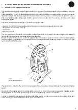
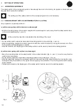
The same overspeed governor (fig. 1) s made up of pulley w th:
- governor wheel (1) w th trapezo dal undercut groove to house the overspeed governor rope
- test grooves for operat on tests (2)
- cam r m (3);
- eccentr c stop (4).
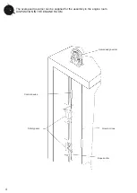
The rope, secured to the clamp of the safety gear and stretched by a we ght, operates the governor wheel (1)
through ts own pressure n the trapezo dal undercut groove.
Bes de the trapezo dal groove, a cam r m (3) w th eccentr c stop (4) s also mounted on the governor wheel.
Such r m allows the pendulum (6) to operate w th an upward/downward osc llat ng mot on, by means of a pul-
ley mounted on a ball bear ng.
The pendulum s drawn to the cam r m by a preloaded tens on spr ng, correspond ng to the scheduled tr pp ng
speed.
By reach ng the tr pp ng speed, the sw ng of the pendulum on the cam becomes so extended, that the osc lla-
t ng dog clutch (8) meets the per pheral gu de of the eccentr c stop, where t s clamped.
A plate (5) appl ed on the pendulum operates the safety sw tch (9) before the mechan cal clamp ng of the pen-
dulum. Through t, the control power of the plant s sw tched off.
F g. 1
Overspeed governor
SKY 200-2


