background image


Assembly and Operating Manual   

Dear customer,   


Congratulations on your choice of a 

factory-assembled model aircraft from the 

SKYANGEL Nano range 

and thank you for 

placing your trust in us.       


Very little preparation work is required to get this 

model ready to fly. To operate your new model 

safely it is important that you read through all of 

the instructions and safety information included 

with your model, before you fly it for the first time.     


The illustrations in this manual show the Silver 

version of the model with factory applied decals. 


The power system 


The model is powered by a brushless outrunner 

motor and ducted fan, both of which are 

factory-installed on the Ready-To-Fly version. 


The motor is connected to the electronic speed 

controller which is factory calibrated on the 

Ready-To-Fly version. All that is required is to 

charge the Li-Po battery, following the safety 

instructions, and connect the battery to the 

electronic speed controller. 


The radio control system     


To fly the Nano F15 you will need a radio control 

system with at least four channels. 2.4GHz radios 

systems are recommended, similar to the unit 

included with our deluxe version.     


The power for the receiver is drawn from the 

electronic speed controller’s integral BEC system. 


The electronic speed controller is located inside of 

the fuselage, in front of the ducted fan. 


When you wish to fly the model, always make sure 

the transmitter is in the “OFF” position. Move the 

throttle stick to the “OFF” position as well. Then 

connect the flight battery to the electronic speed 

controller. 


Switch off in the reverse order: disconnect the 

battery from the electronic speed controller first, 

and then switch off the transmitter. 

 
Glued joints, suitable adhesives 


Foam safe epoxy is recommended and available 

from most reputable model retail shops. 


Trial-fit all parts “dry” before applying glue. 


Follow the recommended curing time suggested 

by the glue manufacturer. Allow the glue to fully 

cure (harden) to the point where the joint can be 

placed under stress. 


Kit contents 


Fuselage, with motor, electronic speed controller 

and servo 

Clear canopy and cockpit   

Left / right wing panels with ailerons 

Left / right horizontal stabilizer with elevators 

Vertical fin 

Accessories 

1 x Li-Po battery, 7.4V 600 mAh 20C   

2 x 6A Brushless ESC (Electronic Speed Controller) 

Y-lead 


Summary of Contents for Nano F15

Page 1: ...35MM Series 2011 Assembly and Operating Manual Nano F15 SPECIFICATION z Length 21 3 5 550mm z Wing Span 15 3 5 395mm z Flying Weight 5 4 5oz 165g ...

Page 2: ...channels 2 4GHz radios systems are recommended similar to the unit included with our deluxe version The power for the receiver is drawn from the electronic speed controller s integral BEC system The electronic speed controller is located inside of the fuselage in front of the ducted fan When you wish to fly the model always make sure the transmitter is in the OFF position Move the throttle stick t...

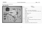
Page 3: ...e Right Wing Panel 4 Tail Set One Left and one Right Horizontal Stabilizer with Elevators 5 Tail Set Two Vertical Fin 6 Cockpit Canopy 7 Fuel tank 8 Missiles 9 600mAh 7 4V 20C Li Po Battery 10 11 Balance Charger 12 Radio Control Transmitter we highly recommend 2 4 GHz system 13 Push rods Set 14 Control rods Set 15 Landing Gear set and Landing Gear Fixed Plate set ...

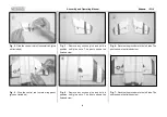
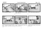
Page 4: ...d Fig 3 Remove any excess glue and hold in position until glue sets The photo shows the finished view Fig 6 Remove any excess glue and hold in position until glue sets The photo shows the finished view Fig 4 Reverse the procedure to the left side The photo shows the finished view Fig 7 Reverse the procedure to the left side The photo shows the finished view ...

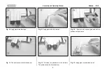
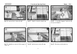
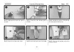
Page 5: ...Fig 11 The photo shows the finished view Fig 9 Apply glue to the Vertical tail Fig 12 Reverse the procedure to the left side The photo shows the finished view Fig 10 Remove any excess glue and hold in position until glue sets Fig 13 Apply glue to the horizontal tail ...

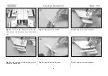
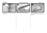
Page 6: ... left horizontal stabilizer The photo shows the finished view Fig 15 Remove any excess glue and hold in position until glue sets Fig 18 Connect the elevator push rod to the servo arm at second hole Fig 16 The photo shows the finished view Fig 19 Assemble the push rod to the horizontal tail control rod ...

Page 7: ...od with screw Fig 23 Assemble the push rod to the wing panel control rod Fig 21 The photo shows the finished view Fig 24 Tighten the control rod with screw Fig 22 Connect the wing panel push rod to the servo arm at third hole Fig 25 Photo shows the finished view ...

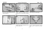
Page 8: ...ight elevator push rod The photo shows the finished view Fig 29 Hold in position until the glue sets photo shows the finished view Fig 27 Apply glue to the missile Fig 30 Apply glue to the fuel tank Fig 28 Apply glue to the wing panel Fig 31 Apply glue to the wing panel ...

Page 9: ...glue to the wing panel Fig 33 Reverse the procedure to the right elevator push rod The photo shows the finished view Fig 36 Hold in position until the glue sets photo shows the finished view Fig 34 Apply glue to the landing gear Fig 37 Reverse the procedure to the left elevator push rod The photo shows the finished view ...

Page 10: ...ct channel wire to the receiver Fig 39 Apply glue to the fuselage glue not included Fig 42 Locate the battery in front of the fuselage Fig 40 Assemble the nose cone to the fuselage The photo shows the finished view Fig 43 Photo shows battery leads connected to the speed controller 38 39 40 41 42 43 ...

Page 11: ...anual 11 Fig 44 canopy is held in place by magnets and can be lifted off Fig 45 The photo shows the finished view Fig 46 Congratulations you have completed the assembly process We hope you enjoy flying your new model 44 45 46 ...

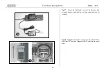
Page 12: ...e flight battery connect the Equalizer lead using and adapter lead matching your charger adapter lead not included Fig 48 Switch the transmitter on and move the throttle stick to the Motor OFF position Diagram MODE 1 right throttle control stick 47 48 ...

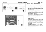
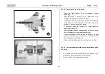
Page 13: ... Pull the elevator stick back towards you c and the trailing edge of both elevators should rise c If either function works in the wrong way correct it using your transmitter s servo reverse facility for that channel Fig 51 Checking the power system Hold the model securely Remove any loose objects such as cloths tools etc from the area in front of the model as they could easily be sucked into the d...

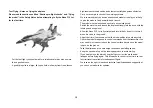
Page 14: ...he position of the flight battery to achieve the correct CG Mark the battery location in the fuselage so that you can be sure of positioning it correctly after recharging Pack scrap pieces of foam around the battery in its final position otherwise there is a danger of it shifting in flight and altering the model s balance Charge the flight battery and the model is ready for flight Fig 53 Access to...

Page 15: ...e motor on and launch the airplane strongly into the wind with the fuselage and wings level Allow the Nano F15 Jet to fly straight and level initially do not try to turn it when it is close to the ground Adjust the trims if necessary so that the model settles into a steady climb Check the model s response to control commands from the transmitter You may need to increase or reduce the control surfa...

Page 16: ...l Electronic Technology Co Limited 5th Floor A3 Building Xinjianxing Technology Industrial Park Fengxin Road Guangming Town Bao an Shenzhen City 518107 China Phone 86 755 33699201 Fax 86 755 33699203 www skyangelrc com ...

Reviews: