D
APPENDIX 4 - SETTING UP POTENTIOMETER INPUTS
The D can be set up to download measurements as raw data or as scaled data in the
user's preferred engineering units. Measurements are always stored as raw data in the
DataHog's memory and calculated into units, if required, at the time of downloading. So if the
full-scale value is changed at any time, the entire memory will be recalculated using the new
values at the next data offload.
Potentiometer inputs on the D are usually used for windvane sensors and generally
labelled as such.. If the D was bought directly from Skye, with its sensors, then all inputs
will have been set up with calibration data already entered, ready for use. However, it is
possible to configure this input for any suitable potentiometer sensor as described below.
The potentiometer input will supply a sensor excitation of nominally 1.3 V, and accept a maximum
signal of +2V. The exact excitation for each D is individually measured and given on
the Hardware Configuration Certificate at the front of the logger manual (only when supplied for
sensors other than a windvane). The potentiometer itself must have a minimum of
1
k
resistance.
A raw data count of 0-12,288 (user scaled as wished) can be set over the whole rotation of the
potentiometer.
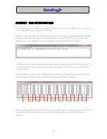
To enter a new full scale value, choose 'Option 9 - Enter AX+B calibration factors' from the
DataHog's Main Menu (see Chapter 3.2.10 in the D manual also). Enter the software
channel number you wish to configure and you will see a submenu displayed.
Item a) in this menu corresponds to voltage channels with hardware channel numbers 1-23. The
potentiometer inputs are essentially special voltage inputs and should be set up as such. The Full
Scale Value is calculated by dividing the sensor output (in units per mV) by the chosen gain, and
multiplying the result by 2000 (see example below).
REMEMBER - VALUES NEED TO BE ENTERED AS 5 DIGITS PLUS A DECIMAL POINT - LEADING
ZEROS CANNOT BE USED.
You will also need to enter the offset count for your sensor. Option 9 will continue to prompt you
for its value. Calculate the offset count by multiplying the sensor offset (see example below) by
the chosen gain and by 9.5. Enter this value and its sign (+ or -).
IN THIS CASE - LEADING ZEROS ARE PERMITTED BUT DECIMAL POINTS ARE NOT.
Pin Connections for a Potentiometer Input
Pin 1
n/c
Pin 2
1.3 V nominal sensor excitation
Pin 3
n/c
Pin 4
potentiometer wiper connection
Pin 5
ground and screen connection
53


