background image

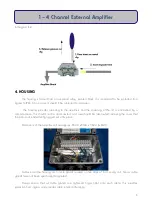
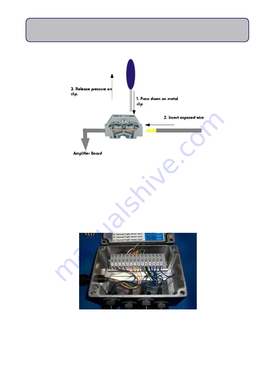
In diagram form: 

4. HOUSING

The housing is formed from an aluminium alloy, painted black. It is considered to be protected from 

ingress to IP65. On no account should it be subjected to immersion.

  The housing provides screening to the amplifiers and the screening of the lid  is  maintained  by  a 

connected wire. This should not be disconnected, and care should be taken whilst removing the cover that 
the wire is not inadvertently tugged out of its place.

Dimensions of the amplifier unit are approx.: 85mm x 81mm x 36mm (LxWxH).

Cables enter the housing via 5 cable glands located on two sides of the housing unit. Sensor cable 

glands have not been specifically designated.

Please   ensure   that   all   cable   glands   are   tightened   finger   tight   onto   each   cable.   This   provides 

protection from ingress, and provides cable retention/fastening.

6

1 – 4 Channel External Amplifier

Summary of Contents for SKP 125 VS

Page 1: ...4 Channel External Amplifier SKP 125 VS Skye Instruments Ltd 21 Ddole Enterprise Park Llandrindod Wells Powys LD1 6DF UK Tel 44 0 1597 824811 skyemail skyeinstruments com www skyeinstruments com Iss 1...

Page 2: ...ems Feel free to contact us via our e mail or any of the methods below Click on the icons to browse to the sites or search for the usernames below Have a Smartphone Scan this QR code to access our web...

Page 3: ...ODUCTION 1 2 TYPICAL APPLICATION 2 2 1 Amplifier 2 3 WIRING POWER DETAILS 3 3 1 Wiring 3 3 2 Sensor Output Power Supply 4 3 3 Connecting to Terminal 5 4 HOUSING 6 5 SPECIFICATIONS 7 6 TROUBLESHOOTING...

Page 4: ...light can be accurately measured e g this may be useful when the maximum light levels are unknown at the outset Our range of amplified sensors have the amplification is built into the sensor housing w...

Page 5: ...X depending on the application It is possible to have different channels providing different output ranges for a given sensor but only one range would be available at any one time There is a maximum o...

Page 6: ...utput cable Grey 9 Sensor cable screens Grey 10 Sensor input grounds Green x 4 11 Channel 1 light sensor Input Blue Serial 12 Channel 2 light sensor Input Blue Serial 13 Channel 3 light sensor Input B...

Page 7: ...0 mol m 2 s 1 SKL 2633 Lux 0 1V 0 150 000 Lux 100 000 Lux SKL 2640 PAR Energy 0 1V 0 600 watts m 2 500 watts m 2 SKL 2650 Pyranometer 0 1V 0 1 500 watts m 2 1 100 watts m 2 If the sensor s is are comp...

Page 8: ...cated on the side of the terminal block Once satisfied that the wire is inserted deep enough release the pressure and the wire will be firmly secured in the terminal Please see the figures below Using...

Page 9: ...isconnected and care should be taken whilst removing the cover that the wire is not inadvertently tugged out of its place Dimensions of the amplifier unit are approx 85mm x 81mm x 36mm LxWxH Cables en...

Page 10: ...0 100 Temperature 20o C to 70o C Power Requirements 0 up to 3V output range 5 15V power supply 0 3 6V output range 9 15V Outputs Custom range specified at time of ordering e g 0 1V 0 5V etc Scaling Cu...

Page 11: ...rminal that has been configured for them Also check that the four output wires are connected to the correct channels in the measuring equipment and that the system is interpreting the output in the co...

Page 12: ...Skye Instruments Ltd 21 Ddole Enterprise Park Llandrindod Wells Powys LD1 6DF UK Tel 44 0 1597 824811 skyemail skyeinstruments com www skyeinstruments com...

Reviews: