background image


161

SJ82 T, SJ86 T

229040ABA

Section 5 – Procedures

5.1   General

The following information is provided to assist you in 
the use and application of servicing and maintenance 
procedures contained in this chapter.

 NOTE

The illustrations shown in this manual are for 
instructional purposes only.  The models and 
components shown may appear somewhat 
different from those on your actual MEWP.

5.1-1  Safety and Workmanship

Your safety, and that of others, is the first 
consideration when engaging in the maintenance of 
equipment. Always be conscious of weight. Never 
attempt to move heavy parts without the aid of a 
mechanical device. Do not allow heavy objects to rest 
in an unstable position. When raising a portion of the 
equipment, ensure that adequate support is provided.

Before performing routine maintenance underneath 
the boom, support it using a maintenance support or 
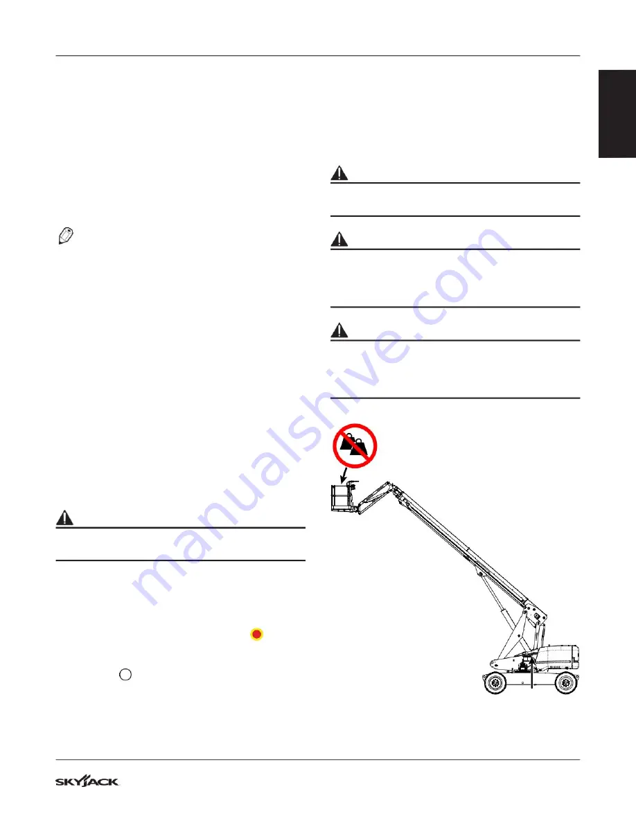
equivalent supporting device.  Refer to Figure 01 and 

5.1-2 How to Install the Boom Maintenance Support

.  

Contact Skyjack Parts to order a maintenance 
support.

 WARNING

Remove all material and personnel from the 
platform while using the maintenance support(s).

1. 

Park the MEWP on a firm, level surface.

2. 

Retract and lower the boom and platform until 
the MEWP is in the stowed position.

3. 

Turn the engine off.

4. 

Pull out the emergency stop buttons

on the 

base controls and on the platform controls.

5. 

Turn the battery disconnect switch to the off 
position

.

After completing any procedure which involves 
modifying, adjusting, or replacing any hydraulic or 
electrical components, perform all of the function tests 
given in your unit’s Operating Manual.

 WARNING

Make sure you maintain three points of contact 
when mounting and dismounting the platform.

 WARNING

Do not operate any platform controls without the 
proper fall protection secured to the designated 
location in the platform.  Failure to do so could 
result in death or serious injury!

 WARNING

Make sure there are no people or obstructions in 
the test area, and there is sufficient space for the 
boom and drive functions required for the given 
procedures.

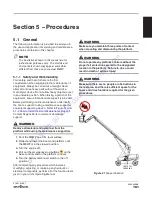
106 757 N
24,000 lbf

Figure 01

 Support location

To 

order 

go 

to 

Discount-Equipment.com

Summary of Contents for SJ82 T

Page 1: ...SERVICE MANUAL TELESCOPIC BOOMS 229040ABA August 2020 ANSI CSA CE AS SJ82 T SJ86 T T o o r d e r g o t o D i s c o u n t E q u i p m e n t c o m...

Page 2: ...Curtis Gehl Pavers Heli Honda ICS PowerGrit IHI Partner Imer Clipper MMD Koshin Rice CH E General Equip ment Amida Coleman NAC Gradall Square Shooter Kent Stanley Tamco Toku Hatz Kohler Robin Wiscons...

Page 3: ...This manual is for MEWPs with serial numbers SJ82 T A402 000 001 A402 999 999 SJ86 T A402 000 001 A402 999 999 T o o r d e r g o t o D i s c o u n t E q u i p m e n t c o m...

Page 4: ...RNING WARNING indicates a potentially hazardous situation which if not avoided could result in death or serious injury CAUTION CAUTION indicates a potentially hazardous situation which if not avoided...

Page 5: ...ydraulic Maintenance Hints 13 1 2 7 Railing Maintenance and Repair 14 1 3 Scheduled Maintenance 15 1 3 1 Service Bulletins 15 1 3 2 Maintenance and Inspection 15 1 3 3 Maintenance Instructions 15 1 4...

Page 6: ...st 54 3 6 Electrical Parts List 57 3 7 Hourmeter Counter Harness CE 62 3 8 Rotary Manifold Port Identification 63 3 9 System and Drive Pump Port Identification 65 3 10 Drive Motors Port Identification...

Page 7: ...L 102 3 46 Electrical Schematic ANSI CSA AS Deutz D2011 103 3 47 Electrical Schematic CE Deutz TCD2 2 104 3 48 Electrical Schematic CE Deutz D2011 105 3 49 Engine Electrical Schematic Deutz TD2 9L 106...

Page 8: ...11 Platform will not Level 153 4 3 12 Brake will not Release 154 4 3 13 Brake will not Engage 154 4 3 14 No Drive 155 4 3 15 Differential Lock will not Engage 155 4 3 16 No High Speed Drive 155 4 3 17...

Page 9: ...4 14 Platform Installation no Jib Boom 192 5 4 15 Platform Control Console Connection 193 5 4 16 Extension Cylinder and Wire Rope Replacement 194 5 4 17 Extension Cylinder and Cable Assembly Removal...

Page 10: ...djustment 247 5 8 5 Turret Rotate Relief Valve Adjustment 248 5 8 6 Platform Level Relief Valve Adjustment 248 5 8 7 Fly Boom Relief Valve Adjustment 249 5 8 8 Test Charge Pump Pressure on Drive Pump...

Page 11: ...ment on the aerial platform at all times Service Maintenance The purpose of this is to provide the customer with the servicing and maintenance procedures essential for the promotion of proper machine...

Page 12: ...y must be immediately tagged and removed from service until proper repairs are completed 1 2 4 Maintenance and Service Safety Tips Maintenance and repair should only be performed by personnel who are...

Page 13: ...nly through the filter opening The use of cloth to strain the oil should be avoided to prevent lint from getting into the system 6 When removing any hydraulic component be sure to cap and tag all hydr...

Page 14: ...bent deformed guardrail sections cracks or broken welds in railing sections damaged pin connections missing pins or broken pin lanyards missing railing hardware loose or missing parts additional hole...

Page 15: ...WP parked on a flat and level surface Disconnect the batteries by disconnecting the main power connectors Repair any damaged or malfunction components before operating MEWP Keep records on all inspect...

Page 16: ...re is no inspection recorded in the last 13 months If you do not obey there is a risk of death or serious injury IMPORTANT The Owner s annual inspection record is located on the scissor assembly It mu...

Page 17: ...all tires for damage wear and correctly aligned B Wheel Tire Assembly No loose bolts Wheel nuts torqued as recommended C PLATFORM Raillings and Gates Correctly attached and no damage or missing compon...

Page 18: ...partment electrical panel Engine wiring harness Rotary manifold wiring 1 6 2 Hydraulic Do a check on these areas and make sure there are no signs of leakage Hydraulic tank filter fittings hoses emerge...

Page 19: ...n of the battery case for damage Clean the battery terminals and cable ends thoroughly with a terminal cleaning tool or wire brush 2 Make sure all the battery connections are tight 3 If applicable che...

Page 20: ...hed with no visible damage Engine fuel leaks B C Make sure that there no fuel leaks at the engine Make sure there is no visible damage WARNING Explosion or fire hazard Do not smoke near the fuel syste...

Page 21: ...B Frequent Inspection For recommended oil change refer to engine manual B Frequent Inspection For the recommended oil change interval and procedure refer to the engine manual 9 Air filter B C Make su...

Page 22: ...the stowed position Do a check on the gauge on the side of the hydraulic oil tank The hydraulic oil level must be at or a small distance above the top mark of the gauge Add oil if it is necessary Ref...

Page 23: ...e estimated task DANGER Explosion or fire hazard Do not smoke near the fuel system If you do not obey there is a risk of death or serious injury Make sure that the fuel filler cap closes tightly Make...

Page 24: ...ed Make sure there are no loose or missing parts Make sure all the fittings and hose connections are tight Make sure there is no sign of hydraulic leakage C Annual Inspection Check the brakes annually...

Page 25: ...xle Oscillation Diagrams 9 Wheel tires B C Do a check on all tire treads and sidewalls for cuts cracks holes and unusual wear Do a check on each wheel for damage and cracked welds Do a check on each l...

Page 26: ...visible damage 6 AC power socket Make sure that the socket is free of dirt or blockages 7 Platform control console B Make sure all switches and controllers are in the neutral position Make sure there...

Page 27: ...d All hoses are correctly tightened and there is no sign of hydraulic leakage Make sure there are no visible cracks in welds or structure and there are no signs of deformation 4 Cable Track B There ar...

Page 28: ...visible damage All fasteners are correctly tightened Make sure that the nuts are correctly tightened and are locked together Make sure that there are no gaps between the springs For the wire rope ten...

Page 29: ...welder and the welder tray are correctly attached There are no loose or missing parts and there is no visible damage There are no loose wires or missing fasteners 4 Cold or arctic weather package The...

Page 30: ...vice technician After repairs are completed the operator must perform a pre operation inspection and a series of function tests again before putting aerial platform into service Prior to performing fu...

Page 31: ...C SWIVEL FEMALE 37 JIC SWIVEL 100R13 H03 FEMALE 37 JIC SWIVEL 45 FEMALE 37 JIC SWIVEL 100R17 H04 FEMALE 37 JIC SWIVEL 45 FEMALE 37 JIC SWIVEL 100R13 H05 FEMALE 37 JIC SWIVEL LONG 90 FEMALE 37 JIC SWIV...

Page 32: ...L FEMALE 37 JIC SWIVEL 100R4 H39 LONG 90 FEMALE 37 JIC SWIVEL FEMALE 37 JIC SWIVEL 100R4 H40 SHORT 90 FEMALE 37 JIC SWIVEL FEMALE 37 JIC SWIVEL 100R16 H43 FEMALE 37 JIC SWIVEL FEMALE 37 JIC SWIVEL 100...

Page 33: ...c Grade 8 280 380 Engine Deutz Engine Mount BOLT Hex head 1 2 13 x 3 75 Grade 5 55 75 Coupling Assembly BOLT M10 40 55 Muffler NUT 40 55 Engine Deutz Engine Mount BOLT Hex head 1 2 13 x 3 75 Grade 5 5...

Page 34: ...7 2 47 5 52 5 M10 x 1 25 49 4 54 6 55 2 61 0 71 5 78 5 78 0 86 0 86 0 94 0 93 0 103 0 M12 x 1 25 90 100 98 109 128 142 139 154 152 168 166 184 M12 x 1 5 86 95 94 104 120 132 133 147 143 158 159 175 M1...

Page 35: ...ubrizing oil grease or uncured Loctite 1374AA Size Torque Type SAE2 SAE 5 SAE 8 Dry Lubed Dry Lubed Dry Lubed 9 16 12 ft lb 70 55 110 80 150 110 Nm 95 75 149 108 203 149 9 16 18 ft lb 80 60 120 90 170...

Page 36: ...2 00 ft lb 104 78 148 111 60 45 Nm 141 106 201 150 6 8 5 1 M16 x 2 00 ft lb 161 121 230 172 68 51 Nm 218 164 312 233 7 7 5 8 M18 x 2 50 ft lb 222 167 318 238 12 9 Nm 301 226 431 323 16 12 M20 x 2 50 f...

Page 37: ...Chart for JIC Size Steel Brass Dash Frac ft lb Nm ft lb Nm Min Max Min Max Min Max Min Max 4 1 4 10 11 13 15 5 6 6 75 9 6 3 8 17 19 23 26 12 15 17 20 8 1 2 34 38 47 52 20 24 27 66 33 10 5 8 50 56 69...

Page 38: ...tial gear every 700 hours Gear box once at 50 hours after every 1000 hours Tighten Gear box screws bolts every 200 hours N A Wheel Nuts every 200 hours Operation Member Conditions Frequency Lubricants...

Page 39: ...eath or serious injury Replace tires with the exact Skyjack approved types only IMPORTANT For proper function of each axle differential all four wheels must have same tire size installed at all times...

Page 40: ...y LCP Locally Concentrated Pressure is a measure of how hard the aerial platform tire tread presses on the area in direct contact with the floor The floor covering tile carpet etc must be able to with...

Page 41: ...e 3 93 in 9 98 cm Rod Diameter 2 95 in 7 493 cm Stroke 255 in 64 77 m Maximum Boom Pressure 3000 psi 207 bar Lift Cylinder Bore 7 48 in 19 cm Rod Diameter 3 93 in 9 98 in Stroke 84 06 in 2 13 m Maximu...

Page 42: ...1 62 m 1 62 m Platform Height Stowed 0 48 m 19 0 48 m 19 0 28 m 0 28 m Overall Railing Height 1 34 m 52 3 4 1 34 m 52 3 4 1 35 m 1 35 m Platform Railing Height 1 09 m 43 1 09 m 43 1 12 m 1 12 m Dimens...

Page 43: ...ion Time Extended 190 220 seconds 190 220 seconds Platform Rotation Time 10 20 seconds 10 20 seconds Boom Up Time 90 100 seconds 90 100 seconds Boom Down Time 90 100 seconds 90 100 seconds Boom Extend...

Page 44: ...s 1200 Low 1600 2600 High Horsepower 2600 rpm intermittent 55 4 kW 75 hp Fuel Type Diesel Fuel Tank Capacity 45 gal 170 3 L Standard Oil Factory Fill 0 F to 115 F 18 C to 45 C SAE 15W 40 API CF CG CH...

Page 45: ...firm level surface Axle oscillation free travel mode drive speed 3 0 mph 4 8 km h max Axle oscillation locked work mode drive speed 0 5 mph 0 8 km h max Axle Oscillation SJ82 T Axle oscillation free t...

Page 46: ...8m or 2 4 m TURRET ROTATION 360 TAIL SWING 60 1 5 m PLA TFO RM ROT ATIO N ANG LE 170 PLATFORM ROTATION RADIUS 63 7 1 62 m OUTSIDE TURNING RADIUS 283 7 18 m OVERALL RAILING HEIGHT 53 1 3 m PLATFORM RA...

Page 47: ...T 86 26 2 m JIB R O M UP 65 MAX WORKING HEIGHT 92 28 m MAX HORIZONTAL REACH 76 10 23 4 m 105 2 67 m BOOM R O M DOWN 12 CHASSIS GROUND CLEARENCE 16 0 4 m JIB LENGTH 66 1 7 m VERTICAL REACH BELOW GRADE...

Page 48: ...49 SJ82 T SJ86 T 229040ABA Section 3 System Component Identification and Schematics T o o r d e r g o t o D i s c o u n t E q u i p m e n t c o m...

Page 49: ...CONNECTED BATTERY FUSE GROUND CIRCUIT BREAKER VOLT METER CAPACITOR POTENTIOMETER SINGLE POLE DOUBLE THROW RELAY TRIPLE POLE DOUBLE THROW RELAY RELAY RELAY DOUBLE POLE DOUBLE THROW SINGLE POLE SINGLE...

Page 50: ...E COUNTER BALANCE VALVE ROTARY ACTUATOR OIL COOLER VALVE COIL BI DIRECTIONAL HYDRAULIC MOTOR TWO POSITION TWO WAY NORMALLY CLOSED VALVE TWO POSITION THREE WAY VALVE THREE POSITION FOUR WAY CLOSED CENT...

Page 51: ...RN 09 YEL 32 GRN BLK 55 YEL PUR 78 RED BLU 106 GRN PINK 10 BLU WHT 33 GRN WHT 56 YEL BLK 79 BRN PUR 107 BLK BLU 11 WHT ORG 34 ORG BLK 57 BRN GRN 80 GREY WHT 108 YEL BRN 12 RED YEL BLK 35 ORG WHT 58 WH...

Page 52: ...olors Protective Ground Protective Earth Green Green Yellow Neutral White Blue Line Single Phase Black Black or Brown or Grey 1789AA Note Standard colors referenced from IEC 60445 2010 Annex A Table 1...

Page 53: ...ght 4H 38 168758 VALVE Control boom retract 4H 39 168756 VALVE Control boom extend 4H 40 159803 VALVE Control platform level down 4H 41 159803 VALVE Control platform level up 5H 23A 159807 VALVE Contr...

Page 54: ...6 N A VALVE Check 3 5 kW generator CV17 159814 VALVE Check 12 kW generator manifold LS CV18 171410 VALVE Check 12 kW generator manifold CV19 N A VALVE Check 12 kW generator CV20 159814 VALVE Check 3 5...

Page 55: ...E Relief main manifold RV2 171385 VALVE Relief swing drive RV3 166047 VALVE Relief platform level RV4 171386 VALVE Relief boom extend RV5 N A VALVE Relief brake manifold RV6 N A VALVE Relief drive RV7...

Page 56: ...mp Torque mode 45CR2 127131 RELAY 12 Volt 40 Amp Torque mode 49CR 127131 RELAY 12 Volt 40 Amp Horn 54ACR 127131 RELAY 12 Volt 40 Amp Cold start 56ACR 127131 RELAY 12 Volt 40 Amp Fuel pump 57ACR 127131...

Page 57: ...H V2 N A COIL 12 Volt Load sense compensator 4H 13 159820 COIL 12 Volt Boom down valve 4H 14 159820 COIL 12 Volt Boom up valve 4H 15 N A COIL 12 Volt Reverse drive valve 4H 16 N A COIL 12 Volt Forward...

Page 58: ...e PL8 170502 LIGHT Amber Water in fuel Base control console PL9 147229 LED BLOCK Red 12 volts Platform control console PL10 170501 LIGHT Green Low capacity Platform control console PL11 170501 LIGHT G...

Page 59: ...ency stop Platform control console S5 138278 SWITCH Ignition emergency pump toggle Base control console S6 138278 SWITCH Ignition emergency toggle Platform control console S8 102853 SWITCH Diagnose to...

Page 60: ...on 3 System Component Identification and Schematics Index No Skyjack Part No Description 170787 HOUR METER CE AS X22 138576 PORT Diagnose Deutz engine X23 138574 CONNECTOR Engine Deutz engine T o o r...

Page 61: ...ss CE 3 7 Hourmeter Counter Harness CE A A B B DESCRIPTION IDENTIFICATION COLOUR CAVITY ID 12 VDC PURPLE 1 HOURMETER H 1 RED 2 COUTNER C 1 BLUE 3 HOUR RESET RH 1 GREEN 4 COUNTER RESET RC 1 WHITE 5 GRO...

Page 62: ...Drive Pump Port 5 To Steer Cylinder L Port 2 To Axle Lock Cylinder Port V9 To Rear Drive Motor Port 10 To Rear Axle Di erential Lock Port 8 To Rear Drive Motor Port 1 To Steer Cylinder R Port 10 To Br...

Page 63: ...Right Port 2 Axle Oscillation Unlock Signal Port 3 Axle Oscillation Cylinder Pressure Port 4 SAHR Brake Release Port 5 Steer Left Port 6 Hydraulic Motor 2 Speed Port 10 Di erential Lock if equipped P...

Page 64: ...dentification Mb To Brake Manifold Ma To Brake Manifold D1 To Hydraulic Tank S To Hydraulic Tank A To Rotary Manifold C1 To Rotary Manifold L To Hydraulic Tank S To Hydraulic Tank P To Pressure Filter...

Page 65: ...nt Identification and Schematics Drive Motors Port Identification 3 10 Drive Motors Port Identification S1 To Rotary Manifold A To Rotary Manifold B To Rotary Manifold D1 To Rotary Manifold T o o r d...

Page 66: ...ntification 2A To Platform Rotator Right 1A To Platform Rotator Left 4A To Bulkhead 1 to T3 2B To Jib Cylinder Extend 1B To Jib Cylinder Retract 3B To Bulkhead 1 to PP 4H 37 Platform Right Rotate Valv...

Page 67: ...ematics No Jib Valve Port Identification 3 12 No Jib Valve Port Identification 1A To Bulkhead 2 3 To Bulkhead 2 2 P To Bulkhead 1 4 T To Bulkhead 1 4H 37 Platform Right Rotate Valve 4H 36 Platform Lef...

Page 68: ...To Brake Cylinders V1 Brake Release Override AL To Rotary Manifold LS To Main Manifold T To Tank T4 M2 To Drive Pump V3 Brake Hand Pump CV13 Check Valve V8 Loop Flush Valve PR1 Pressure Reducing Valv...

Page 69: ...Cylinder LB To Lift Cylinder BLS To Brake Manifold PP To Rotary Manifold RB To Swing Drive RA To Swing Drive P2 To Emergency Pump EA To Extend Cylinder P1 To High Pressure Filter EB To Extend Cylinde...

Page 70: ...42 Flow Enable Valve 5H 32 Turret Rotate Left Valve 5H 24A Steer Left Valve 5H 23A Steer Right Valve 4H 13 Boom Lower Valve 4H 14 Boom Up Valve 5H 33 Turret Rotate Right Valve 4H 38 Boom In Valve PLA...

Page 71: ...Shuttle Valve DSV1 Pressure Compensating Valve RV3 Relief Valve DSV3 Pressure Compensating Valve GP2 Test Port DSV2 Pressure Compensating Valve V4 Pilot Valve V5 Pilot Valve RV2 Relief Valve RV1 Relie...

Page 72: ...PIN 1 45 YL OR PIN 2 02 6 WH SPLICE 3 PIN 1 55 YL PR PIN 2 02 9 WH SPLICE 3 PIN 1 15 BL PIN 2 02 7 WH SPLICE 3 PIN 3 02 8 WH SPLICE 3 PIN 4 16 WH BK 00 WH 12GA 03 GN PR 12GA 108 YL BN 14GA PIN 1 24A...

Page 73: ...SE CONTROL BOX LAYOUT VALVE TO BOOM LIFT INSERT WIRE 19 TO AVAILABLE TB 19 INSERT WIRE 09 TO AVAILABLE TB 09 10A 09 01A 55 09 74 13 14 60 10 21 20 29 32 33 38 39 40 41 59 76 02 02 02 17 02 02 162A 162...

Page 74: ...02 02 11 09 17 02 02 02 77 103 76 55 54A 54A 41 40 39 38 33 32 29 59 59 20 21 10 60 60 01 01 14 13 74 09 09B 121 121 165 80 1389 165 IINSERT HARNESS WIRE 165 TO TB 165 BASE CONTROL BOX LAYOUT VALVE TO...

Page 75: ...AVITY WIRE NO COLOUR DESCRIPTION 1 35 ORANGE WHITE JIB UP 2 02 WHITE SPLICE 2 GROUND CAVITY WIRE NO COLOUR DESCRIPTION 1 37 WHITE RED BLK ROTATE CCW 2 02 WHITE SPLICE 1 GROUND CAVITY WIRE NO COLOUR DE...

Page 76: ...POSITION 18 WIRE 18 POSITION 19 WIRE 19 POSITION 20 WIRE 20 POSITION 21 WIRE 21 POSITION 22 WIRE 22 POSITION 23 WIRE 23 POSITION 24 WIRE 24 BASE PLATFORM CONNECTIONS POSITION 1 WIRE 1 POSITION 2 WIRE...

Page 77: ...ed Tilt Override Limit Switch Black White Black 29 59 29 59 LS3 Fly In Limit Switch Black 09 Black 09B Black White 121 09 121 09B ANSI CE LS4 Boom Angle Dual Load Limit Switch Black White Black 09 122...

Page 78: ...27 26 25 12 10 1 2 3 4 5 6 7 8 9 11 04 04 04 02 02 02 17A 20B 08 65 13 38 26 128A 17 08A 36A 28 26A 32 42 14 15 DSIG XSIG YSIG CSIG 38A 34A 16 33 59 D34 A D35 A D36 A D37 A D20 B 118 82 UNUSED WIRES I...

Page 79: ...11 76 77 54A 54A 74 02 02 PIN 1 02 WHITE PIN 2 106 GREEN PINK PIN 3 96 WHITE GREY PIN 4 76 BROWN BLUE PIN 5 74 GREEN GREY PIN 6 PLUGGED PIN 7 PLUGGED PIN 8 PLUGGED PIN 9 PLUGGED PIN 10 105 GREEN BROWN...

Page 80: ...3 11B RELAY CONNECTOR PIN OUT TO AIR BOX TO ENGINE GLOW PLUG POWER FEED STUD 30 11A RED 85 54A BLK EGR CONNECTOR PIN OUT CAVITY 1 07 WHITE CAVITY 2 02 BLACK 86 11 WHT 87 11B RED 54A BLK 11 WHT BASE CO...

Page 81: ...09 09 09 76ACR 60CR 79CR 01ACR 56ACR 20A 03 03B 86A 86CR 86 03B INSERT WIRE 09 INTO TERMINAL BLOCK POSITION 09 INSERT WIRE 02 FROM VALVE HARNESS INTO TERMINAL BLOCK POSITION 02 WIRE 03B 117326 144637...

Page 82: ...9 08 78 85A 57A 85 02 S22 GEN 04A 04 85 04 04A 02 08CR 57A 04A 02 1 2 3 4 5 6 7 8 9 10 11 12 24 23 22 21 20 19 18 17 16 15 14 13 1 2 3 4 5 6 7 8 9 10 11 12 24 23 22 21 20 19 18 17 16 15 14 13 13 21 24...

Page 83: ...A B C D E F G H V Z Y X W 85 SJ82 T SJ86 T 229040ABA 3 28 Platform Work Light M168636AB 81A 02 81A 02 7A 7A T o o r d e r g o t o D i s c o u n t E q u i p m e n t c o m...

Page 84: ...WHITE GROUND TO POSI AIR CONTROLLER POSITIVE AIR SHUT OFF MODULE 10 PIN CONNECTOR PLUG PIN 1 BLACK 401 PIN 6 BLUE 403 PIN 2 EMPTY PIN 7 WHITE 02 PIN 3 RED 403A PIN 8 WHITE 408 PIN 4 GREEN 402 PIN 9 E...

Page 85: ...VDC LS5 0V PL1 500LB PL2 OVERLOAD LS4 SUPPLY DIN1 DIN2 SUPPLY DOUT1 DOUT2 AIN2 4 20mA AIN1 4 20mA DOUT3 SCOUT1 SCIN1 SAFETY CONTACTS 3AMP LOAD ZONE BORDER SIGNAL SIGNAL LOAD REDUNDANT SCOUT2 SCIN2 SCO...

Page 86: ...1C 21B BLACK 21C 02 21B 57A 02 WHITE 02 S5 IGN 57A COOLER 78CR 60CR 21CR 49CR 79CR 45CR1 45CR2 01ACR 59CR CE 86CR 10A 09 01A 55 09 74 13 14 10 21 20 29 32 33 38 39 40 41 59 76 02 02 02 17 02 02 162A 1...

Page 87: ...IT 3 02 CC REV M1 B DRIVE MOTOR 14 7 CC 0 90 CIR 40 6 CC 2 48 CIR CB13 5000 PSI 10 1 C6 C7 AXLE LOCK OUT CYLINDERS CB12 5000 PSI 10 1 C9 FRONT AXLE SAHR BRAKE CYLINDER C8 4WD FRONT AXLE STEERING CYLIN...

Page 88: ...8 02 08 02B 24 R10 250 R11 250 R8 250 R9 250 04 02 C L 22 23 21 19 18 17 16 15 14 13 20 24 35 34 33 32 31 30 29 28 27 26 25 12 10 1 2 3 4 5 6 7 8 9 11 04C 04C 04C SPLICE 02 02 02 02 17A 20B 08F 65 13...

Page 89: ...11 250 R8 250 R9 250 60 02 C L 22 23 21 19 18 17 16 15 14 13 20 24 35 34 33 32 31 30 29 28 27 26 25 12 10 1 2 3 4 5 6 7 8 9 11 04C 04C 04C SPLICE 02 02 02 02 17A 20B 08F 65 13 38 26 27 39 128A 17 08A...

Page 90: ...2 3 4 WHT RED LEFT 5 WHT YEL RIGHT 08 RED YEL WHT RED BLU YEL WHT BLK BLU WHT 24 BLU BLK 23 60 27A 118 02 08 02B 24 R10 250 R11 250 R8 250 R9 250 04 02 C L 22 23 21 19 18 17 16 15 14 13 20 24 35 34 33...

Page 91: ...SLOT 35A 2 1 NC 42 20 BLACK 02 RED BP2 20 02 162BCR2 82 02 118 162B 162B 26BCR 26 26B 26C 26D CANH CANL 02 09 26B 26C 09B 02 76 KEY AT1 SENSOR CONNECTION PIN 1 09 YELLOW PIN 2 28 GREEN PIN 3 02 WHITE...

Page 92: ...49 49A 09 02 02 162A 02 21A 21 02 09 108 01A 01ACR 59CR 60 09 02 07 02 86CR D10A D01A 09 09A 56A 56ACR 77CR 77 01 54 01A D10A 1 79 56B 54 56C 128 GLOW FUEL MIL TEMP OIL P WIF 02 02 79 78 90 90 99A 99B...

Page 93: ...6B 26C 77 02 KEY 76 162A KEY 10B 14 38 39 38A 14A 10A 39A 01A 162B 19 01A 01A 162A X22 TT1 HOURMETER S3 E STOP 123ACR 24P FEMALE MAIN HARNESS 07CR 09CR 78CR 60CR 57ACR 21CR 49CR 79CR 01ACR S12 BOOM S1...

Page 94: ...4 23 22 21 20 19 18 17 16 15 14 13 13 14 15 16 17 18 19 20 21 22 23 24 12 11 10 9 8 7 6 5 4 3 2 1 09 28 02 49A 02 SPARE 05 10 07 02 35B 37B R2 SetPt 7 ohm 09 02 02 45 45A 45CR1 45CR2 45 128 128A 128B...

Page 95: ...MAIN HARNESS PL6 PL4 PL3 PL7 PL5 PL8 10A 10D 123A 02 01A 123CR 123 59CR1 1 1 D10A 2 02 10D 10A 59 J3 B 09B KEY 00 CANL CANH 57D 20 26D 57DCR 09 57B 57D 57A D57D CANL CANH BP5 54 77 403ACR 35A 2 1 NC...

Page 96: ...2 82 162BCR2 118 162B 26BCR 26D 26C 26B 26 CANH CANL 02 09 26B 26C 77 02 KEY 76 X22 TT1 HOURMETER S3 E STOP 123ACR 24P FEMALE MAIN HARNESS 07CR 09CR 78CR 60CR 57ACR 21CR 49CR 79CR 01ACR S12 BOOM S14 T...

Page 97: ...33 R1 6ohm D 2 3 1 D 2 3 1 J5 162BCR2 118 02 162B 82 26BCR 26D 26B 26 26C 09F AT1 SENSOR CONNECTION PIN 1 09 YELLOW PIN 2 28 GREEN PIN 3 02 WHITE PIN 4 128 BLACK YELLOW CONNECTOR J1 PIN 1 PLUGGED PIN...

Page 98: ...CANH CANL 02 09 26B 26C 09F 77 01B 05 02 10B KEY 12A X22 S3 E STOP 123ACR 24P FEMALE MAIN HARNESS 07CR 09CR 78CR 60CR 57ACR 21CR 49CR 79CR 01ACR S12 BOOM S14 TELE S17 JIB S15 LEVEL DIAGNOSE S8 CB3 CB...

Page 99: ...ALE A 1 2 3 4 5 6 7 8 9 10 11 12 24 23 22 21 20 19 18 17 16 15 14 13 13 14 15 16 17 18 19 20 21 22 23 24 12 11 10 9 8 7 6 5 4 3 2 1 09 28 02 49A 02 SPARE 05 10 07 02 42 37B R2 SetPt 6 ohm 09 02 02 45...

Page 100: ...POSITION 20 A POSITION 17 B POSITION 16 B RED POSITION 2 A POSITION 14 B POSITION 12 B POSITION 1 A PURPLE BLACK BLACK POSITION 13 B POSITION 5 A GREEN RED YELLOW BLACK POSITION 19 B POSITION 20 B PO...

Page 101: ...5 02 D76 D74 D27A 12 9 02 162A SUPPR 08CR1 08 20D 02 02 02 04A 45CR1 59 LS2 HIGH DRIVE TILT OVERRIDE 29 FLY IN LS LS3 CLOSED NORMALLY NORMALLY CLOSED 79 79CR LOW 2 1 14 11 4 10 17 21 18 24 23 JMPR 99...

Page 102: ...JIB UP DOWN S21 S18 IN OUT TELESCOPE BOOM TURRET JOYSTICK A2 A3 SELECTOR SPEED CTRL DRIVE STEER JOYSTICK A1 R 02 Gnd 02 L L S48 DRIVE TORQUE SWITCH LOW TORQUE 45 45 45 07A 02 02 17 17 20E 10A 10A R1...

Page 103: ...OOTSWITCH PL7 74 55 02 D76 D74 D27A 12 9 02 162A SUPPR 08CR1 08 20D 02 02 02 04A 45CR1 59 LS2 HIGH DRIVE TILT OVERRIDE 29 FLY IN LS LS3 CLOSED NORMALLY NORMALLY CLOSED 79 79CR LOW 2 1 14 11 4 10 17 21...

Page 104: ...RD K01 14 RD K01 14 RD 00 14 WH 00 12 WH 00 12 WH 00 14 WH 00 14 WH 00 14 WH 56B 14 RD 56B 14 RD 103 18 BK 103A 18 WH 56A 18 WH 84 18 WH T ONLY 203 18 BK 57A 16 BK 74 18 WH 105 18 WH 104 18 BK 201 18...

Page 105: ...16 BK A18 16 WH A33 16 BK A16 16 WH A05 16 BK A04 16 WH A46 16 BK A03 16 WH A32 16 BK A02 16 WH A07 18 BK A23 18 BK A35 18 BK A45 18 BK A23 18 BK A35 18 BK A45 18 BK A24 18 BK A25 18 BK A27 18 BK A28...

Page 106: ...104 18 BK 76A 18 WH 96 18 WH 76 18 BK 99 18 BK 90 18 BK 54 18 BK K15 18 BK 82 K82 18 BK A40 18 BK A22 18 BK K20 18 BK K19 18 BK 09 18 BK K58 18 BK A07 18 BK A50 18 BK A41 18 BK 39 38 24 54 44 41 57 2...

Page 107: ...4 RD 00 14 WH 00 12 WH 00 12 WH 00 14 WH 00 14 WH 00 14 WH 00 14 WH 56B 14 RD 56B 14 RD 56A 18 WH 57A 16 BK 74 18 WH 105 18 WH 104 18 BK A58 18 BK 76A 18 WH 96 18 WH 76 18 BK 99 18 WH 90 18 BK 09 16 B...

Page 108: ...le more quickly than any other method This manual cannot cover all possible troubles and deficiencies that may occur If a specific trouble is not listed isolate the major component in which the troubl...

Page 109: ...ce if defective 8 Loose or broken wire 07 from base emergency stop switch S3 to base key S2 Check continuity Replace if defective 9 Open or defective key select switch S2 Close switch Replace if defec...

Page 110: ...o Ignition E pump switch S5 Check continuity Replace if defective 3 Loose or broken wire 12 from base key switch S2 to base connector plug A pins 2 3 Check continuity Replace if defective 4 Loose or b...

Page 111: ...rom relay 08CR to plug B pin 14 Check continuity Replace if defective 6 Loose or broken wire 57A in boom cable B or its connectors Check for continuity between pin 14 on cable B Check for loose or cor...

Page 112: ...7ACR Check relay Replace if defective 6 Loose or broken wire 09 from base terminal block to relay 09CR Check continuity Replace if defective 7 Loose or broken wire 03A from circuit breaker CB3 to rela...

Page 113: ...ry to telematics pin 4 Check continuity Replace if defective 3 Loose or broken wire 07 from S3 base Emergency stop switch to 57DCR pin 86 Check continuity Replace if defective 4 Loose or broken wire 5...

Page 114: ...ive 8 Loose or broken wire 56B from relay 56ACR to 12 pin connector J1 pin 3 Check continuity Replace if defective 9 Defective relay 56ACR Check continuity through contacts of relay Replace if defecti...

Page 115: ...wire 11B from relay 54ACR to glow plugs Check continuity Replace if defective 5 Loose or broken wire 54A from base terminal strip to relay 54ACR Check continuity Replace if defective 6 Loose or broke...

Page 116: ...Replace if defective 4 Loose or broken wire 10A from basket rotation switch S16 to level switch S15 Check continuity Replace if defective 5 Loose or broken wire 10A from level switch S15 to jib switch...

Page 117: ...ve 4 2 8 No Movement from Base Control Console No Boom Up 1 Loose or broken wire 10A from ignition pump switch S5 to boom switch S12 Check continuity Replace if defective 2 Defective boom switch S12 C...

Page 118: ...place if defective 2 Open resistor R2 Check resistor for 7 ohms If no resistance found replace resistor 3 Loose or broken wire 10B from resistor R1 to turret rotate switch S13 Check continuity Replace...

Page 119: ...harness plug to turret rotate left valve 4H 33 Check continuity Replace if defective 9 Defective turret rotate left valve coil 4H 33 Check continuity and resistance through coil Replace if defective...

Page 120: ...ace if defective 2 Defective platform rotate switch S16 Check continuity through switch while activating rotate left function between wires 10A and 36 If no continuity found replace switch 3 Open or d...

Page 121: ...ht valve 4H 37 Check continuity Replace if defective 9 Loose or broken wire 02 from platform terminal block to platform rotate right valve 4H 37 Check continuity Replace if defective 10 Defective plat...

Page 122: ...oose or broken wire 02 from platform terminal block to jib up valve 4H 35 Check continuity Replace if defective 10 Defective jib up valve coil 4H 35 Check continuity and resistance through coil Replac...

Page 123: ...el Up 1 Loose or broken wire 10A from ignition pump switch S5 to platform level switch S15 Check continuity Replace if defective 2 Defective platform level switch S15 Check continuity through switch w...

Page 124: ...02 from turret harness pin plug platform level down valve 4H 40 Check continuity Replace if defective 7 Defective platform level down valve coil 4H 40 Check continuity and resistance through coil Rep...

Page 125: ...and 08A If no continuity found replace switch 10 Loose or broken wire 08A from footswitch S11 to valve driver pin 16 Check continuity Replace if defective 11 Loose or broken wire 04 from platform term...

Page 126: ...continuity Replace if defective 2 Defective platform level switch S19 Check continuity through switch while activating level up function between wires 08 and 40 If no continuity found replace switch...

Page 127: ...own NOTE Boom Down may be disabled by the dual load zone system and or overload system if equipped Please first ensure the boom is fully retracted and there are no faults in the overload system 1 Loos...

Page 128: ...tage present with foot on footswitch check section 5 for OCM pin voltage reference 7 Loose or broken wire 32 from valve driver pin 20 to plug A pin 14 in platform control console Check continuity Repl...

Page 129: ...ose or broken wire 33 from base terminal block to turret harness plug pin 11 Check continuity Replace if defective 11 Loose or broken wire 33 from turret harness plug pin 11 to turret right valve 4H 3...

Page 130: ...oose or broken wire 02 from turret harness plug to telescope in valve 3H 38 Check continuity Replace if defective 15 Defective telescope in valve coil 3H 38 Check continuity and resistance through coi...

Page 131: ...t with foot on footswitch check section 5 for OCM pin voltage reference 3 Loose or broken wire 42 from valve driver pin 21 to plug B pin 24 in platform control console Check continuity Replace if defe...

Page 132: ...platform terminal block Check diode Replace if defective 5 Loose or broken wire 36A from platform terminal block to valve driver pin 17 Check continuity Replace if defective 6 Loose or broken wire 37...

Page 133: ...noperative Mid and High Deutz D2 9L 1 Loose or broken wire 90 from base terminal block to connector J2 pin 5 Check continuity Replace if defective 2 Loose or broken wire 90 from connector P2 pin 5 94...

Page 134: ...ay 79CR Check continuity Replace if defective 7 Loose or broken wire 02 from base terminal block to relay 79CR Check continuity Replace if defective 8 Loose or broken wire 90 from relay 79CR to base t...

Page 135: ...tive 6 Loose or broken wire 02 from base terminal block to relay 78CR Check continuity Replace if defective 7 Loose or broken wire 90 from relay 78CR to base terminal block Check continuity Replace if...

Page 136: ...continuity and resistance through coil Replace if defective 4 2 14 No Drive and Steer NOTE Aerial platform will not drive or steer if it is tilted and off limit switches 1 Loose or broken wire 4 from...

Page 137: ...e reference 4 Loose or broken wire 15 from valve driver pin 23 to plug B pin 4 in platform control console Check continuity Replace if defective 5 Loose or broken wire 15 in cable B or its connectors...

Page 138: ...ve joystick A2 to platform terminal block Check continuity Replace if defective 2 Open or defective diode D23 in platform terminal block Check diode Replace if defective 3 Loose or broken wire 23 from...

Page 139: ...if defective 8 Loose or broken wire 59 in boom cable B or its connectors Check for continuity between pins 15 on cable B Check for loose or corroded connections on cable connectors Replace if wire is...

Page 140: ...E Aerial platform must be level to drive elevated 1 Loose or broken wire 09 or 02 from base terminal block to angle transducer tilt switch AT1 Check continuity Replace if defective 2 Misadjusted no ou...

Page 141: ...Replace if wire is defective 6 Loose or broken wire 17 from base plug B pin 6 to valve driver pin 15 in platform control console Check continuity Replace if defective 7 Defective valve driver channel...

Page 142: ...witches to base terminal block Check continuity Replace if defective 6 Loose or broken wire 121 from base terminal block to boom down and boom extend cut out relays CR121 and 121CR2 Check continuity R...

Page 143: ...nd resistance through coil Re place if defective 4 2 22 No boom down Function from Base or Platform Consoles CE AS 1 Loose or broken wire 13 from base terminal block to load sense dual load zone modul...

Page 144: ...tage present when operating down function check section 5 for module information 3 Loose or broke wire 13A from load sense dual load zone module white connector J4 pin 5 to harness plug pin 3 Check co...

Page 145: ...pressure compensator valve 3H V1 Check valve Replace if defective 6 Plugged or defective high pressure filter F1 Check filter Replace if plugged or defective 4 3 3 No Main Boom Up 1 Stuck or defective...

Page 146: ...3 Stuck or defective shuttle valve SV1 Clean valve Check O rings on valve Check opera tion of valve Repair or replace valve as required 4 Stuck or defective check valve CV4 Clean valve Check O rings o...

Page 147: ...ion of valve Repair or replace valve as required 2 Stuck or defective boom extend valve 3H 39 Clean valve Check operation of valve Repair or replace valve as required 3 Stuck or defective check valve...

Page 148: ...red 7 Stuck or defective counterbalance valve CB5 Clean valve Check O rings on valve Repair or replace valve as required 8 Return valve V5 stuck in the closed position or is defective Clean valve Chec...

Page 149: ...n 1 Stuck or defective proportional flow enable valve 2H 42 Clean valve Check O rings on valve Check opera tion of valve Repair or replace valve as required 2 Stuck or defective check valve CV9 Clean...

Page 150: ...a tion of valve Repair or replace valve as required 3 Stuck or defective check valve CV8 Clean valve Check O rings on valve Check opera tion of valve Repair or replace valve as required 4 Stuck or def...

Page 151: ...n valve Check O rings on valve Check opera tion of valve Repair or replace valve as required 2 Defective or misadjusted pressure reducing valve PR1 Set valve to specifications Check O rings and clean...

Page 152: ...if defective 2 Defective or misadjusted drive relief valve RV6 See section 5 for drive pump set up procedures Reverse Drive 1 Defective pump displacement control 4H 15 Check control Replace if defecti...

Page 153: ...ve Check opera tion of valve Repair or replace valve as required 3 Stuck or defective check valve CV3 Clean valve Check O rings on valve Check opera tion of valve Repair or replace valve as required 4...

Page 154: ...e axle cylinders C6 and C7 Check seals on cylinder Replace as necessary Replace cylinder if defective 3 Counterbalance valves CB12 or CB13 out of adjustment or are defective Clean valve Check O rings...

Page 155: ...s lost its calibration Refer to calibration procedure for recalibration of load cell 2 Load cell circuit not operating Check Voltage across 1 ohm resistors 161 and 162 in base control console 02 02 16...

Page 156: ...wire 162B 13A or 39A All safety contacts will be disabled opened Stowed Position all functions are available Off limits boom extended and or boom above 10 No functions and overload alarm pulses with...

Page 157: ...in boom cable A or its connectors Check for continuity between pins 13 on cable A Check for loose or corroded connections on cable connectors Replace if wire is defective 7 Loose or broken wire 13 pl...

Page 158: ...ts to order a maintenance support WARNING Remove all material and personnel from the platform while using the maintenance support s 1 Park the MEWP on a firm level surface 2 Retract and lower the boom...

Page 159: ...ist with this procedure 1 Raise the boom to an angle of 40 40 2 Open the engine side cowling Remove and set aside the fixed cowling from the engine side of the boom There are six sets of hardware to r...

Page 160: ...must be on the inside of the turret 7 Push the lock pin through the hole in the maintenance support Make sure the detent ball comes all the way out the other side IMPORTANT Do not lower the main lift...

Page 161: ...the following information Active Function Being Used Part Number and Serial Number Restore the Factory Default Settings Output Calibrations Tresh Max Ramp etc I O Status CANBus Status 5 2 2 User Inte...

Page 162: ...ion Channel Names DRIVE REV Fn01A Drive Reverse DRIVE FWD Fn01B Drive Forward ROTATE L Fn02A Turret Rotate Left ROTATE R Fn02B Turret Rotate Right BOOM DOWN Fn03A Main Boom Down BOOM UP Fn03B Main Boo...

Page 163: ...Enabled DI 11 0 or 1 High Speed Drive Enable Limit Switch Output Adjustable Parameter Description PWM 1 25 to 75 Drive Reverse PWM 2 25 to 75 Drive Forward PWM 3 21 to 35 Turret Rotate Left PWM 4 21 t...

Page 164: ...L NUMBER ENTER PASSWORD 51 1 FLASHING ENTER PASSWORD 510 0 FLASHING SET LRNG B C PRESS SELECT FLASHING SELECT MODEL PRESS SELECT FLASHING MENU SELECT MENU SELECT MENU SELECT MENU SELECT SELECT MULTIFN...

Page 165: ...ED Ai1 to Ai3 DISPLAYED Ai4 to Ai6 DISPLAYED Do1 to Do5 DISPLAYED Do6 to Do8 DISPLAYED PWM1 to PWM2 DISPLAYED PWM3 to PWM4 DISPLAYED PWM5 to PWM6 DISPLAYED PWM7 to PWM8 DISPLAYED PWM9 to PWM10 DISPLAY...

Page 166: ...OW THRESH Fn05B VALUE THRESH Fn06A VALUE THRESH Fn06B VALUE FLASHING XXXX XX THRESH Fn0XX VALUE FLASHING MODE XX XX LTD FUNCTIONS OFF XXXX XX THRESH MAXOUT LOWRNG RAMPUP RAMPDN Fn0XX VALUE FLASHING XX...

Page 167: ...le 12 volts Platform over steer axle Test between pin 4 and 02 wire Pin 5 12 volt output on wire 20B to load sense dump valve when any function selected Test between pin 5 and 02 wire while selecting...

Page 168: ...put from wire 36A Test between pin 17 and 02 wire Pin 18 12 volt input from angle sensor on wire 28 12V 5 degrees Test between pin 18 and 02 wire Pin 19 Diff lock enable toggle switch ANSI CSA CE Plat...

Page 169: ...Pin 30 Accelerator input Signal wire green wire from boom speed controller Proportional voltage 5 volts slow speed up to 7 5 volts fast speed Test between pin 30 and 02 wire while operating telescope...

Page 170: ...7 25V WIRE L GND O2 WIRE L GND O2 TELESCOPE IN TELESCOPE OUT 250 OHMS 250 OHMS R9 R8 R10 R11 250 OHMS 250 OHMS P1 32 FLY TOGGLE SWITCH WIRE 38A P1 32 WIRE 38A PIN 32 4 83V 7 25V TELESCOPE IN TELESCOP...

Page 171: ...lts full stroke Left 4 1 0 5 Volts full stroke Boom Elevation Y axis Neutral Position 4 2 4 8 Volts Up 4 9 8 5 Volts full stroke Down 4 1 0 5 Volts full stroke 12 Volts Volts Drive A2 Controller Drive...

Page 172: ...nabled 100 Flashing Off Pulsing Off Enabled Disabled Enabled 100 in Work Mode Flashing Pulsing Pulsing Pulsing Disabled Disabled Disabled 100 in Travel Mode Flashing Pulsing Off Pulsing Disabled Enabl...

Page 173: ...off on off enable enable enable 1 0 over 748 339 disable disable disable disable over 20 12 12 0 pulsing 1hz off enable enable disable 1 1 up to 695 315 allow allow allow allow up to 18 8 12 0 off off...

Page 174: ...on 1 Ensure the aerial platform is on firm level ground 2 Fully retract and lower the boom 3 Turn the engine off 4 Pull out both emergency stop buttons and the flip the engine enable switch to the on...

Page 175: ...Trip Point 1 is being calibrated Wait for the red LED to stop flashing this indicates that the calibration point has been stored Calibrate Trip Point 2 11 The yellow LED will remain solid and the red...

Page 176: ...earance and zero drag Fly Boom Shim 1 32 Feeler Gauge Wear Pad 5 Extend and retract the fly boom through the entire range of motion and observe for loose points NOTE Always maintain squareness between...

Page 177: ...sections out See 5 4 6 Platform and Jib Boom Removal If the machine does not have a jib boom just the platform is removed Before beginning place the machine in the proper shut down position parked on...

Page 178: ...box M62067AA 2 Remove the auxiliary AC receptacle box if its harness is bundled with the other harnesses Remove the harness clamps M62191AA 3 Open the control console lid and disconnect the jib and pl...

Page 179: ...the platform rotary actuator Use a suitable container or rags to catch any oil spillage Cap hoses and ports to keep them clean 9 Remove the hoses and wire cable bundle from the P clamps on the side o...

Page 180: ...king nearby Place it close enough to the end of the main boom so the control cables can be reconnected in the event boom repositioning is required 5 4 7 Platform Removal no Jib Boom Before removing th...

Page 181: ...or in the box M62021AA 7 Pull all harnesses through the cable guard on the swivel joint 8 Remove the hoses and wire cables from the P clamp on the side of the fly boom 9 Using suitably rated lifting e...

Page 182: ...IMPORTANT Be aware that the short length of control cables connected to the platform control box limits boom movement Connect the jib and platform rotate harness as shown on the Platform Controls Wir...

Page 183: ...bear the weight of the fly boom ahead of the machine Attach a lifting sling to the tip of the fly boom Lift it up slightly then remove the bottom wear pad M62256AA 5 Lift slide the fly boom out 2 3 of...

Page 184: ...nd place a piece of tape over the switch hole The tape prevents the switch from being damaged as the fly boom is removed M62254AA 4 Place a suitable stand that can bear the weight of the mid boom abou...

Page 185: ...ng equipment slide the mid boom section slowly into the platform end of the main boom Be careful not to damage the wear pads 2 When it is about 1 3 of the way in install the bottom wear pad Apply Loct...

Page 186: ...ntil the holes in the boom tip and the e chain support bracket line up 5 Install the top and side wear pads and shims in the mid boom nose Apply Loctite 242 or 243 to the wear pad fasteners 6 Install...

Page 187: ...form assembly 2 Using suitable lifting equipment move the platform into place 3 Install the main pivot bolt pin flat washer and hex nut Tighten to the correct torque 4 Install the bolts that secure th...

Page 188: ...nector in the bottom of the platform control box Make sure the wires can reach the terminal block on the left hand side of the box 3 Tighten the strain relief connector locknut to secure it M62022AA 4...

Page 189: ...vent hydraulic system contamination by capping all hydraulic connections after disconnecting Sample warning text 5 4 17 Extension Cylinder and Cable Assembly Removal Place the boom in a horizontal 0 p...

Page 190: ...he washers and spacers then put the hex nut back on one full nut thread to temporarily hold the wire rope in place 7 Once the wire ropes are slackened remove the boom flange pins and fasteners NOTE Th...

Page 191: ...ll the cylinder out M62271AA 14 Flip the wire rope terminal plate over so the tapered end faces the counterweight end of the machine Flipping it over makes it easier to remove with the cylinder M62272...

Page 192: ...angled or caught on other components 2 Orient the wire ropes correctly Identify which cable ends go to the platform end and which go to the counterweight end of the machine The tapered end of the wire...

Page 193: ...do not get tangled 10 Install the counterweight end of the wire ropes into the anchor points Install one hex nut on each anchor to secure it M62279AA Counterweight end Wire Ropes 11 Install the flange...

Page 194: ...ension 16 Install the boom end cover 5 4 19 Proper Wire Rope Tension The wire rope assembly is tensioned correctly when the disc springs are fully compressed 1 With the jam nut removed use the flat on...

Page 195: ...a full inspection of the wire ropes at the start of the 10th year of wire rope life They must be inspected every 2 years if not replaced at that time Perform a visual inspection annually If a wire ro...

Page 196: ...r to measure boom angles Multi meter with continuity setting Level 8 9 10 11 12 LS1 6 LS2 7 LS4 LS6 4 LS3 5 LS5 M62347AA 1 2 3 Top View Front of Machine Side View of Boom and Turret 1 Fly Boom Section...

Page 197: ...eight shown over steering axle 1 LS1 Limit Switch 2 Steering Axle 3 Counterweight LS1 is mounted on the rotary manifold in the base frame M62362AA LS1 location on rotary manifold some parts hid den fo...

Page 198: ...ith the multi meter Continuity is indicated when the turret is rotated past 90 Check both clockwise and counterclockwise directions 5 4 23 High Speed Drive Tilt Override Limit Switch LS2 LS2 detects w...

Page 199: ...he multi meter probes on terminal positions 09 Black and 29 Black white Black 09 Black White 29 M62361AA 29 09 LS2 terminal connections 6 Lower the boom below horizontal Verify the switch roller is no...

Page 200: ...fully 2 Place the boom in a horizontal position or slightly less than 0 3 Extend the boom outwards 4 ft 1 2 m At this point the limit switch has tripped and the contacts should be open 4 Locate the te...

Page 201: ...not allow the boom to further lift or extend into the 500 lb 227 kg zone 1 when overloaded M62357AA 1 Automatic platform load sensing When not equipped with automatic platform load sensing ANSI machin...

Page 202: ...nes Wire 121 Black White and 09 Black Standard load sensing ANSI machines Wire 121 Black White and 09B Black Black 09 Black 09B Black White 121 M62360AA 09 121 09B ANSI CE LS4 terminal connections 6 L...

Page 203: ...d the system changes from the high to the low capacity zone LS5 is the upper limit switch on the platform end of the main boom M62354AA LS5 location on main boom NOTE Make sure the switch roller rotat...

Page 204: ...mp on the side of the mid boom and its contact is open 4 Place the multi meter probes on terminal positions shown below as equipped Automatic platform load sensing CE machines Wire 122 Black White and...

Page 205: ...o raise the boom Check Switch Operation 1 Position the main boom horizontal Use a level to verify 2 Place a digital protractor on a clean surface on the underside of the main boom Calibrate it to 0 ho...

Page 206: ...ler Adjustment Procedure 1 Position the boom angle at 57 from horizontal 2 Loosen the limit switch mounting screws 3 Position the switch so that the roller is just touching the master cylinder link an...

Page 207: ...8 Reinstall the housing screwing it in fully then backing it off by one quarter turn 5 5 2 Adjust the Turret Rotation Gear Backlash NOTE The adjustment of the backlash must be performed on a flat leve...

Page 208: ...types 5 5 4 Change the Swing Drive Oil NOTE The oil change must be performed on a flat level surface 1 Remove the plug from the fill port 1 2 Place a suitable container under the drain port 2 3 Remov...

Page 209: ...tant grease 9 Re connect the batteries with the positive and negative connector cables ensure the clamps make good contact 5 5 6 Turret Rotation Gear Bolt Torque Sequence WARNING Maintaining proper to...

Page 210: ...d red or green LED will be continually blinking Red LED Green LED Red LED Green LED 9 Program the tilt switch a Press and release the set to zero button 3 times Observe LED flash codes as shown below...

Page 211: ...xit program mode and return to normal operation using the previously stored data c Press and release the set to zero button 3 times d If the 5 second period has expired prior to completion repeat step...

Page 212: ...g teeth Make sure to allow clearance as the turret assembly rotates 4 Position the indicator arm or shaft so that the pointer touches the bottom surface of the turret weldment CHASSIS TURRET Check Axi...

Page 213: ...s in work mode and overloaded To reset the counter 1 Locate the terminal block with the integrated fuse holder inside the base control box 2 Using any standard automotive fuse insert it into the slot...

Page 214: ...low all engine oil to drain into the container WARNING Dispose of oil in accordance with local and federal regulations 6 Install the oil drain plug with a new seal ring and tighten firmly 7 Remove the...

Page 215: ...ir Filter Engine specifications require that this procedure be performed more often if dusty conditions exist Refer to the engine manual CAUTION Perform this procedure with the engine off 1 Remove the...

Page 216: ...f actuator relay 3 44 523926 4 7 3 2 Short circuit to ground of actuator relay 4 45 168 3 3 1 8 Sensor battery voltage error signal range check is high 46 168 4 3 1 8 Sensor battery voltage error sign...

Page 217: ...rol Short circuit to battery Water pump control PWM 79 523914 4 7 2 1 Glow plug control Short circuit to ground Water pump control PWM 82 1235 14 2 7 1 CAN Bus 2 CAN_C reports Bus error for engines 8L...

Page 218: ...AT1OG1Vol 140 523941 9 7 6 7 Timeout error BAM to packet for CAN Receive Frame AT1OGCVol2 141 523942 9 7 6 7 Calibration message 1 of the after catalyst Nox sensor has failed 142 523943 9 7 6 7 Timeo...

Page 219: ...rror of CAN Transmit Frame UAA1 on CAN 2 Control burner air pump 360 523982 0 7 3 7 Powerstage diagnosis disabled High battery voltage 361 523982 1 7 3 7 Powerstage diagnosis disabled Low battery volt...

Page 220: ...k low or fan speed too low 462 523602 0 2 3 8 High fan speed warning threshold exceeded 463 523602 0 2 3 8 High fan speed shut off threshold exceeded 464 97 3 2 2 8 Sensor error water in fuel signal r...

Page 221: ...Check of missing injector adjustment value programming IMA injector 1 560 523896 13 1 5 8 Check of missing injector adjustment value programming IMA injector 2 561 523897 13 1 5 8 Check of missing in...

Page 222: ...ttery low side 597 523615 4 135 Metering Unit Fuel System Short circuit to ground low side 598 523615 3 1 3 5 Metering unit short circuit to battery 599 523615 4 1 3 5 Metering unit short circuit to g...

Page 223: ...tic fault check to report the plausibility error in rail pressure monitoring 640 523612 12 555 Diagnostic fault check to report the error due to torque comparison 641 523612 12 555 Diagnosis of curr p...

Page 224: ...e sensor plausibility error 755 523919 0 6 9 4 DPF burner air pump pressure sensor pressure above upper shutoff threshold 758 523919 1 6 9 4 DPF burner air pump pressure sensor pressure below lower sh...

Page 225: ...range check low 825 523009 9 2 5 3 The pressure relief valve PRV has reached the number of allowed activations 826 523470 2 1 4 6 Pressure relief valve is forced to open perform pressure increase 827...

Page 226: ...sor voltage above upper limit 878 157 4 1 4 7 Sensor error rail pressure Sensor voltage below lower limit 881 523633 11 1 4 9 Longterm adaption factor below threshold 882 523633 11 1 4 9 Nox conversio...

Page 227: ...alid range 929 523722 8 6 9 1 Detect faulty PWM signal from Supply Modul 930 523721 8 6 8 9 DEF supply module temperature duty cycle in failure range 931 523721 8 6 8 9 Urea supply module temperature...

Page 228: ...below lower physical threshold 994 105 3 1 2 8 Electrical error charged air temperature Signal range check high SRC 995 105 4 1 2 8 Electrical error charged air temperature Signal range check low 996...

Page 229: ...re upstream DOC signal range check high 1045 4768 4 6 8 3 Electrical error exhaust gas temperature upstream DOC signal range check low 1047 3248 4 6 8 5 Sensor error particle filter downstream tempera...

Page 230: ...le valve 4 1 6 1 7 8 Voltage below thresh old 1239 523984 3 7 8 8 UB7 Short circuit to battery error of actuator relay 7 1241 523986 4 1 7 6 UB6 Short circuit to ground actuator relais 6 1242 523987 4...

Page 231: ...4 Timeout error CAN message ComMSMoFOvR1TO error memory Slave 1299 523788 0 6 5 5 Wastegate plauisibility error off CAN transmit message 1300 523788 0 6 5 5 Timeout Error of CAN Receive Frame ComTrbCh...

Page 232: ...Physical range check high for ECU temperature 1402 4769 2 6 8 4 Sensor exhaust gas temperature OxiCat downstream normal operation plausibility error 1403 4769 2 6 8 4 Sensor exhaust gas temperature Ox...

Page 233: ...relay open load only CV56B 1488 523718 3 6 7 6 SCR mainrelay short circuit to battery only CV56B 1489 523718 4 6 7 6 SCR mainrelay short circuit to ground only CV56B 1661 524116 9 1 9 4 Timeout error...

Page 234: ...reshold 1701 524135 0 9 5 8 DPF soot load exceeds the shutoff threshold 1702 524135 14 9 5 8 DPF soot load exceeds the service request threshold 1703 524135 0 9 5 8 DPF soot load exceeds the warning t...

Page 235: ...88 12 8 1 4 Turbocharger wastegate internal electrical error 1792 1188 13 8 1 4 Turbocharger wastegate learning process aborted 1793 1188 6 8 1 4 Turbocharger wastegate current above maximum threshold...

Page 236: ...is sent and shown 1 on the screen of the Deutz engine display module 2 found below the engine control console and identified by the flashing standstill lights on the base 3 and platform 4 controls x...

Page 237: ...ll switch is turned on 4 On the engine display module 2 press and hold the middle button 9 below the regeneration symbol for 7 seconds WARNING Do not touch hot engine components Serious injury can occ...

Page 238: ...e hydraulic oil to drain into the container WARNING Dispose of hydraulic oil in accordance with local and federal regulations 5 Install the oil drain plug with new seal ring and tighten it firmly 6 Re...

Page 239: ...console and extend the boom slightly approximately 12 30 cm to achieve low speed drive 5 Drive the MEWP forward or reverse The pressure gauge reading should be 400 psi Stop the aerial platform Follow...

Page 240: ...5 minutes 4 Check the reading on the gauge standard pressure should be 330 psi and follow the next steps for adjusting pressure if needed 5 Locate the load sense compensator 2 on the system pump 6 Loo...

Page 241: ...inutes 4 Without driving steer fully to one direction and then check the reading on the gauge Standard pressure should be 3050 psi Follow the next steps for adjusting the pressure if needed 5 Locate t...

Page 242: ...to one direction and then check the reading on the gauge Standard pressure should be 3250 psi Follow the next steps for adjusting pressure if needed 5 Locate the system relief valve RV1 2 O R 1 R V 1...

Page 243: ...activate the turret rotate to obtain a pressure reading on the gauge 10 Disengage the turret transport lock 5 8 6 Platform Level Relief Valve Adjustment 1 Locate the GP2 port 1 on the main manifold 2...

Page 244: ...rease the pressure and counterclockwise to decrease the pressure 7 Tighten the lock nut on the fly boom relief valve RV4 once 1500 psi is observed on the gauge You must fully extend the boom to activa...

Page 245: ...n the engine off 9 Remove the pressure gauge from the port cap the port and re plug the brake solenoid power cable 5 8 10 Test Reverse Drive Pressure on Drive Pump NOTE Make sure the charge pump press...

Page 246: ...or 9 o clock position Shut off the engine 2 Remove the plug and check the oil level The oil level should be even with the bottom of the plug hole Add oil if needed Refer to 2 10 Hydraulic Specificatio...

Page 247: ...il specifications Fill 5 9 5 Change the Oil in the Axle Gearbox 1 Place a suitable container under the gearbox 2 Remove the fill plug 3 Remove the drain plug to allow oil to drain into the container F...

Page 248: ...5 Repeat the procedure on the opposite axle 5 9 7 Oscillating Cylinder Bolt Replacement If upon inspection it is determined that the oscillating cylinder bolts have missing or damaged torque seal the...

Page 249: ...slowly loosen the bleeder screw to release any trapped air within the cylinder then tighten it again Slowly loosen the oscillating axle cylinder hoses to release the pressure then disconnect them ful...

Page 250: ...tall the base cover and remove the block of wood 11 Turn the engine on and let it run for a few minutes to pressurize the cylinder then turn it off again 12 Check the oil level using the hydraulic tan...

Page 251: ...Result The steer axle should be locked 2 Drive one of the steer tires up onto a 6 15 cm block or curb Result An appropriate tilt of the MEWP chassis should occur 3 Retract the fly boom while in tilt p...

Page 252: ...cowling and locate the turret ring gear grease fitting beside the hydraulic tank 2 Pump grease into the fitting and continue pumping until new lube appears continuously around the grease seal lip of t...

Page 253: ...es 1 Open the axle cover plates and locate the grease fittings 2 Pump grease into the grease fittings 5 10 4 Grease the Drive Shaft 1 Locate the grease fittings on the drive shaft u joints and pump gr...

Page 254: ...Curtis Gehl Pavers Heli Honda ICS PowerGrit IHI Partner Imer Clipper MMD Koshin Rice CH E General Equip ment Amida Coleman NAC Gradall Square Shooter Kent Stanley Tamco Toku Hatz Kohler Robin Wiscons...

Page 255: ...T o o r d e r g o t o D i s c o u n t E q u i p m e n t c o m...

Reviews: