SECTION 3, Page 1
SJIII Series - The Conventional
s 129919
Section 3
System Component Identification
And Schematics
Table Of Contents
3
Symbols & Charts
Figure 3.1-1.
Relay Function Chart ............................................................................................................... 2
Figure 3.1-2.
Tilt Switch Usage Chart ............................................................................................................ 3
Figure 3.1-3.
Electrical Symbol Chart ........................................................................................................... 4
Figure 3.1-4.
Hydraulic Symbol Chart ........................................................................................................... 5
Hydraulic System
Figure 3.2-1.
Hydraulic Schematic Parts List ................................................................................................ 7
Figure 3.2-2.
Hydraulic Schematic - Model 3220/4620 ................................................................................. 9
Figure 3.2-3.
Hydraulic Schematic - Model 3226/4626/4632 ...................................................................... 10
Figure 3.2-4.
Hydraulic Schematic - Model 46XX ....................................................................................... 11
Figure 3.2-5.
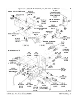
Hydraulic Manifold Component And Port Identification ......................................................... 13
Electrical Diagrams And Schematics
Figure 3.3-1.
Electrical Schematic And Diagram Parts List ......................................................................... 14
Figure 3.3-2.
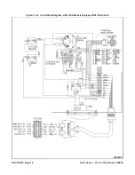
Operator’s Control Box Diagram (ANSI/CSA) - No Options ................................................... 18
Figure 3.3-3.
Operator’s Control Box Diagram (ANSI/CSA) - All Options .................................................... 19
Figure 3.3-4.
Operator’s Control Box Diagram (ANSI/CSA-EE RATED) - No Options ................................. 20
Figure 3.4-1.
Electrical Panel Diagram (ANSI/CSA) - No Options ............................................................... 21
Figure 3.4-2.
Electrical Panel Diagram (ANSI/CSA) - All Options ................................................................ 23
Figure 3.4-3.
Electrical Panel Diagram (ANSI/CSA EE-RATED) - No Options .............................................. 26
Figure 3.4-4.
Electrical Panel Diagram (ANSI/CSA EE-RATED) - All Options .............................................. 28
Figure 3.4-5.
Electrical Panel Diagram (CE) - All Options ........................................................................... 29
Figure 3.5-1.
Electrical Schematic Diagram (ANSI/CSA) - No Options ....................................................... 31
Figure 3.5-2.
Electrical Panel Diagram (ANSI/CSA) - All Options ................................................................ 33
Figure 3.5-3.
Electrical Panel Diagram (ANSI/CSA EE Rated) - NoOptions ................................................ 35
Figure 3.5-4.
Electrical Panel Diagram (ANSI/CSA EE Rated) - All Options ................................................ 36
Figure 3.5-5.
Electrical Schematic Reference (CE) - All Options ................................................................. 37
AI
Summary of Contents for SJIII Compact 3215
Page 206: ......
Page 207: ...Reliable lift solutions by people who care www skyjack com...


