background image

TM

ZB12032


December 2007 

Page 55

Loading/Unloading 

Section 2 - Operation

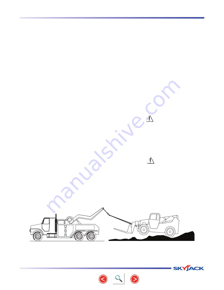
2.13-2  Towing the Telehandler

impORTANT

Use this procedure only to remove 

• 

telehandler from mud or other places 
where it cannot move under its 
own power. When possible, repair 
telehandler on site.

Always chock wheels of the disabled 

• 

telehandler to prevent accidental 
movement while preparing for towing. 
This is especially important if the failure 
occurs on an incline.

Before towing, ensure there are no 

• 

obstructions around or between 
telehandler and towing vehicle.

The spotter must maintain a safe 

• 

distance and must always be visible to 
the operator inside telehandler’s cab.

Ensure the towing vehicle, chains, tow 

• 

bar, etc., are suitable for the job. The 
telehandler weight is stamped on the 
serial number nameplate.

Lower or raise boom and outriggers (if equipped) 

1. 

enough  so  that  front  tie-down  points  are  fully 
accessible.

Carefully fasten tow chains to tie-down points on 

2. 

either front or rear of telehandler frame.

Remove chocks from wheels.

3. 

Enter cab and fasten seatbelt.

4. 

Ensure transmission gear selector is in ‘neutral’ 

5. 

and the transmission lever neutral lock switch is 
in the ‘N’ neutral position.

Start the engine.

6. 

Release park brake.

7. 

Start towing the telehandler while operating the 

8. 

steering and brakes.

Move telehandler to a compact level surface.

9. 

Apply park brake.

10. 

Turn  off  engine  and  remove  key  from  ignition 

11. 

switch.

wARNiNG

Ensure that you maintain three points of 

contact to mount/dismount the cab.

Dismount from telehandler.

12. 

Chock  or  block  wheels  to  prevent  telehandler 

13. 

from rolling.

CAUTiON

Bad  traction  can  cause  telehandler  or 
towing  vehicle  to  slide.  Grades  can 
require  additional  distance  to  stop 
the  telehandler.  Be  careful  if  traction 
conditions are bad or the machine on an 

incline.

Fig 2-14  Towing the telehandler

from front tie-down points

Summary of Contents for ZB12032

Page 1: ...MODELS ZB12032 Operating Manual ZOOM BOOM Telehandlers Part No 402286AB A September 2010...

Page 2: ...rth America Toll Free 1 800 965 4626 Toll Free Fax 1 888 782 4825 Email parts skyjack com Parts Service Europe Unit 1 Maes Y Clawdd Maesbury Road Industrial Estate Oswestry Shropshire SY10 8NN UK Phon...

Page 3: ...ult in minor or moderate injury It may also be used to alert against unsafe practices important IMPORTANT indicates a procedure essential for safe operation and which if not followed may result in a m...

Page 4: ...ctions 17 2 2 Major Components 18 2 3 Major Assemblies 19 2 3 1 Frame 19 2 3 2 Cab 19 2 3 3 Boom Assembly 19 2 3 4 Attachment 19 2 4 Serial Number Nameplate 19 2 5 Component Identification 20 2 5 1 Op...

Page 5: ...2 10 Refueling Procedure Diesel Fuel Only 49 2 11 Use of the Capacity Chart 50 2 11 1 Examples on Reading the Capacity Chart 51 2 12 Pipe Grappler Attachment Operation 52 2 12 1 Handling Loads Using...

Page 6: ...TM Page 6 December 2007 ZB12032 Notes...

Page 7: ...the labels on the telehandler with the labels found within this manual If any labels are damaged or missing replace them immediately Service Policy and Warranty SKYJACK warrants each new ZB series te...

Page 8: ...ions You as a careful operator are the best insurance against an accident Therefore proper usage of this telehandler is mandatory The following pages of this manual should be read and understood compl...

Page 9: ...ction No part of telehandler or payload should be brought closer to any energized overhead electrical conductor with nominal phase voltage rating as specified below Voltage Distance 750 to 150 000 10...

Page 10: ...operation Stop engine and remove ignition key to prevent unauthorized use Block wheels WEAR all the protective clothing and personal safety devices issued to you or called for by job conditions DO NOT...

Page 11: ...r is on a truck forklift or other device or vehicle If operation in areas with holes or drop offs is absolutely necessary ensure that all 4 wheels or outriggers if equipped have contact with firm surf...

Page 12: ...position possible for the vehicle KEEP forks close to the ground when in motion to increase telehandler stability and decrease potential for injury to others When fully stopped lower forks completely...

Page 13: ...y extended The further out the boom is extended the less load telehandler can support USE CAUTION when placing loads at high elevations and on downhill slopes BE AWARE of all obstructions while travel...

Page 14: ...ollover protection structure ROPS Do not make any modification to this structure If damaged the cab cannot be repaired It must be replaced STUNT driving and horseplay are prohibited ALWAYS USE FRONT s...

Page 15: ...nd one foot or one hand and two feet are in contact with the telehandler or the ground at all times during entering and exiting WARNING Operator should not use any telehandler that does not appear to...

Page 16: ...TM Page 16 December 2007 ZB12032 Notes...

Page 17: ...erate this telehandler without proper authorization and training Failure to avoid this hazard could result in death or serious injury 2 1 2 Operator s Responsibility for Maintenance WARNING Maintenanc...

Page 18: ...2032 Section 2 Operation 2 2 Major Components ZB12032 Telehandler ZB12032 Telehandler Boom Assembly Pipe Grappler Attachment Attachment Tilt Cylinder Operator s Cab Front Axle and Tire Rear Axle and T...

Page 19: ...e telehandler 2 3 3 Boom Assembly The boom is mounted on the frame and consists of two telescoping boom sections 2 3 4 Attachment The attachment is a material handling device attached to the boom The...

Page 20: ...tment Ride Control Adjustment Fore Aft Lock Lever Seat The telehandler seat is equipped with devices which allow for the adjustment of seat height and distance from the controls Adjust the seat so tha...

Page 21: ...heel Turn the steering wheel to the left or right to steer the telehandler in the corresponding direction Three steering modes are available refer to Section 2 9 4 6 Heater Fan Switch If Equipped This...

Page 22: ...d hold right side switch while pulling joystick backward To close secondary clamp press and hold right side switch while pushing joystick forward 9 Light Switches If Equipped These switches turn light...

Page 23: ...rake Select rocker switch backward position when operating on a slope While in this position the transmission will remain in gear 18 Steer Mode Switch This switch has three positions to allow selectio...

Page 24: ...isplays level of fuel in fuel tank 24 Transmission Oil Temperature Gauge This gauge displays transmission oil temperature 25 Parking Brake Indicator Light This light indicates parking brake switch is...

Page 25: ...e IMPORTANT The operator must understand and follow the step by step instructions to test all telehandler functions The operator should make a copy of the Operator s Checklist see Table 2 6 and fill o...

Page 26: ...o also inspect all switches electrical and hydraulic components 2 7 1 Labels Refer to the labels section in this manual and determine that all labels are in place and are legible 2 7 2 Electrical Main...

Page 27: ...ver inflated tire can explode and may cause death or serious injury Check all tire treads and sidewalls for cuts cracks punctures and unusual wear Check each wheel for damage and cracked welds Check e...

Page 28: ...cleaning tool or wire brush 3 Ensure all battery connections are tight 4 If applicable check battery fluid level If plates are not covered by at least 1 2 13 mm of solution add distilled or demineral...

Page 29: ...or serious injury DANGER Enginefuelsarecombustible Inspectthe telehandler in an open well ventilated area away from heaters sparks and flames Always have an approved fire extinguisher within easy reac...

Page 30: ...minimum and maximum marks on the sight glass Add oil as needed Hydraulic Return Filter Ensure filter element is secure Ensure there are no signs of leakage or visible damage 2 7 9 Boom Ensure there a...

Page 31: ...age Ensure attachment is properly positioned and secured refer to Section 2 12 for attachments 2 7 12 Grease Points Maintaining properly greased components is essential for good performance and servic...

Page 32: ...nders top and bottom outrigger pins slave cylinders top and bottom 3 Using a creeper slide under the frame to locate grease fittings and pump grease in the following drive shaft U joint front and rear...

Page 33: ...d other important documentation are enclosed in manual storage box Ensure manual is legible and in good condition Always return manual to the manual storage box after use Operator s Cab Controls WARNI...

Page 34: ...tests again before putting telehandler into service Prior to performing function tests be sure to read and understand Section 2 9 Start Operation WARNING Ensure there are no personnel or obstructions...

Page 35: ...backward Result The reverse alarm should sound and reverse light if equipped should turn on Test Lights If Equipped 1 Use a spotter to check if all the lights are working well The spotter should maint...

Page 36: ...r should stop 7 Shift transmission lever backward and release the service brake pedal slowly Result Telehandler should move backward 8 Depress service brake pedal slowly Result Telehandler should stop...

Page 37: ...rd Result Telehandler should move in the chosen direction producing a turning circle with front wheels pointing in the opposite direction to the rear wheels 6 Steer the telehandler straight ahead unti...

Page 38: ...ect rocker switch to backward position for crab steering 13 Turn the steering wheel to the left or right and drive forward Result Telehandler should move in the chosen direction with both front and re...

Page 39: ...ed motion is clear 2 Ensure parking brake switch is off 3 Drive the telehandler on a slope 4 Depress service brake pedal slowly until telehandler stops 5 Select parking brake rocker switch to on posit...

Page 40: ...extend and boom extension indicators are visible 4 Tilt attachment forward by pressing and holding the thumb button while moving joystick forward Result Attachment should tilt forward 5 Tilt attachme...

Page 41: ...level Test Frame Level Lock 1 Ensure parking brake switch is on 2 Raise boom above 45 boom angle and attempt leveling the frame to the right or to the left Result Frame level lock light should illumi...

Page 42: ...elehandler wind and weather conditions the presence of unauthorized personnel other possible unsafe conditions WARNING Anoperatorshouldnotuseanytelehandler that does not appear to be working properly...

Page 43: ...eed Twist the transmission hand grip to select higher gear until the desired speed is reached 5 Select appropriate gear for the task being performed Select lower gear when transporting load traveling...

Page 44: ...over steering NOTE Loss of electrical power will allow front steering only Figure 2 7 Front Steering Crab Steer The crab steer is used for maneuvering into tight spots Figure 2 8 Crab Steering 2 9 5...

Page 45: ...he load behind front face of the tires Never drive the telehandler with the boom raised Avoid panic braking Apply brakes smoothly for a controlled stop to prevent toppling the load Ensure not to excee...

Page 46: ...arning flags during the day and flares or flashing lights at night 1 Position telehandler on a firm and level surface WARNING Always engage parking brake before leaving the cab 2 Engage parking brake...

Page 47: ...flame and other sources of ignition authorized by your employer and supervisor To minimize possible static electricity fires ensure filler nozzle touches rim of filler opening to aid the dissipation...

Page 48: ...e capacity chart is for the specific telehandler model and attachment 2 Determine the weight of the load to be lifted 3 Determine the height where the load is to be picked or placed 4 Determine the re...

Page 49: ...capacity regions the smaller of the two capacity values must be used Note The is a sample capacity chart only DO NOT use this capacity chart Use chart inside cab Fig 2 11 Capacity Chart Examples Exam...

Page 50: ...e load and both primary and secondary clamps open 3 Insert forks under center of the load and raise it 5 to 10 inches 4 Tilt forks backwards IMPORTANT Ensure that the load rests completely against the...

Page 51: ...must be sealed during transport 2 13 1 Loading and Tie down Ensure telehandler is level prior to loading 1 Fully lower and retract boom and raise outriggers 2 if equipped Ensure ramps are correctly po...

Page 52: ...quipped 1 enough so that front tie down points are fully accessible Carefully fasten tow chains to tie down points on 2 either front or rear of telehandler frame Remove chocks from wheels 3 Enter cab...

Page 53: ...id heater 3 Service and park brake activated transmission disconnect 3 ROPS FOPS operator compartment 3 Anti freeze 3 4 wheel drive 3 External rear view mirrors 3 Automatically activated spring parkin...

Page 54: ...height 32 ft 9 75 m Maximum forward reach 16 ft 10 in 5 13 m Curb weight standard machine with open cab 27 820 lbs 12 619 kg Maximum capacity 10 000 lbs 4 535 Kg Wheelbase 120 in 305 cm Gradeability 8...

Page 55: ...e originally supplied with this equipment can adversely affect stability Therefore replace tires only with the exact original Skyjack approved type Failure to operate with matched approved tires in go...

Page 56: ...ed Water Engine T r a n s m i s s i o n Type ATF Dexron III Capacity 6 3 gal 24 L T r a n s m i s s i o n A x l e s Differential SAE 80W 90 GL 5 and 1 0 Liter of Friction modifier FM7099 per axle Plan...

Page 57: ...ter A 220B Engine Coolant A Muffler and Exhaust A Engine Compartment A Engine Oil Level A Fuel Leaks A Hydraulic Pump A Belts A Fuel Tank A Hydraulic Tank A Hydraulic Oil A Hydraulic Return Filter A B...

Page 58: ...Driving and Service Brake Functions Steer Cylinder Assembly Test Steering Frame Test Frame Level Lock Wheel Tire Assembly Test Accelerator Pedal Hydraulic Test Boom and Attachment Functions Cylinders...

Page 59: ...Warning Identifies load suspension location on forks 2 B C D E F Boom Extension Indicate the extension of the boom 3 GREASE GREASE DEC 005R Grease Grease point 4 ZoomBoom Zoom Boom logo 5 12032 Model...

Page 60: ...n 1 12032 Model Number Product Identifier Model number will vary may not be as shown 2 DEC 101 GREASE INSIDE Grease Inside Grease points 3 Skyjack Logo Small Skyjack logo black 4 DEC 005L GREASE Greas...

Page 61: ...ety precautions when filling tires DEC 007 Tire Pressure Warning Maintain correct tire pressure 6 Tire Pressure Inflate tires to 80 psi maximum 7 A TTENTION TORQUE PER SEQUENCE 50 100 FT LBS DRY AND T...

Page 62: ...BS DRY AND THEN PER SEQUENCE 450 500 FT LBS DRY 1 2 10 9 3 4 5 6 7 8 DEC 304 Torque sequence and values Indicates torque sequence and torque values 4 Skyjack Logo Skyjack logo black 5 Turbo Turbo Tele...

Page 63: ...INS RECOMMENDED ETHYLENE GLYCOL COOLANT AND WATER NEVER DILUTE THE COOLANT OR THE LIFE OF THE ENGINE MAY BE SERIOUSLY SHORTENED CHECK OR ADD COOLANT AT THE RESERVE TANK NOT THE RADIATOR CUMMINS ENGINE...

Page 64: ...L ONLY Diesel Fuel Only Refill fuel tank with diesel fuel only 2 HYDRAULIC OIL ALL WEATHER TYPE SEE OPERATORS SERVICE MANUAL DEC 009 Hydraulic Oil Refill Hydraulic oil tank with all weather type hydra...

Page 65: ...AKES Pedal Response Clean Mud and Debris from Brake Pedal Assembly ELECTRICAL All Exposed Wiring Proper Operation of All Gauges Charging System Ammeter Voltmeter ENGINE Hoses Belts Fluid Levels Leaks...

Page 66: ...IN E Hoses Belts Fluid Levels Leaks TIRES Gouges cuts puncture s 13 00 and 14 00 X24 Grader Lug 65 PSI Unloade d Rims Examine for Cracks Distortio n Lock Ring Assembl y OPER ATING INSTR UCTIO NS Centr...

Page 67: ...Telehandler is equipped with a back up alarm 6 DEC 013A WARNING No Riders No Riders Warning Absolutely no riders on telehandler IMPORTANT THIS VEHICLE IS EQUIPPED WITH A CUMMINS QSB ELECTRONIC ENGINE...

Page 68: ...DAMAGE FOLLOW PROCEDURE BELOW VEHICLE BATTERY DISCONNECTION 1 Ensure the Keyswitch has been OFF for at least 1 Minute 2 Disconnect the POSITIVE Battery Cable 3 Disconnect the NEGATIVE Battery Cable BA...

Page 69: ...TM Page 72 December 2007 ZB12032 Notes...

Page 70: ...TM ZB12032 December 2007 Page 73 Notes...

Page 71: ...TM Page 74 December 2007 ZB12032 Notes...

Page 72: ...the State of California to cause cancer birth defects and other reproductive harm Battery posts terminals and related accessories contain lead and lead com pounds chemicals known to the State of Cali...

Page 73: ...Reliable lift solutions by people who care www skyjack com...

Reviews: