background image

01/11/2017

9/36

E_MH_Mounting_instructions_Skylux_Climalux

u


Nearly all silicone products affect 

the polymethyl methacrylate or poly-

carbonate sheets. Purchase silicone 

types that are safe for polymethyl 

methacrylate or polycarbonate pro-

ducts (guarantee certificate).

u


The fumes from this putty may 

never evaporate in the slots of the 

sheet. The ventilation openings as well 

as the sides of the end profiles may 

not be closed off. The silicone should 

always be allowed to release fumes 

freely.

u


Some seals contain softening agents 

(as used in certain types of rubber, 

PVC, polyurethane, etc.) that may 

cause small cracks. Use only approved 

seals.

u


Do not use black or dark-coloured 

seals to prevent heat accumulation.

u


A lead slab may be placed on the 

seals but may not rest against the 

sheets.

u


Some paints, varnishes and wood 

protectors affect the polymethyl 

methacrylate or polycarbonate sheets. 

Never use lubricants to put the seals 

into the profiles.

u


Never spray insecticide directly on 

to the sheets. Synthetic sheets can be 

damaged by these products.

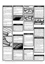
2. SILICONE, SEALS AND

WOOD PROTECTORS

u


Observe the safety instructions 

that apply to work on roofs.

Polycarbonate sheets: Very 

IMPORTANT! The side which is 

protected against UV radiation 

must always be installed facing 

the exterior or the sky. The “sun 

side” is indicated on the protec-

tion film.

u


The plastic tape or the provisional 

aluminium tape will only ensure the 

sheets are free from dust while being 

shipped. These should be removed! 

Adjusted aluminium tape or end pro-

files must be used.

u


The load-bearing structure must 

be strong and stable. (See the regu-

lations that apply to the timber and 

metal construction industry.) Cross 

supports may be required depending 

on the type of sheet used. Only spe-

cific maximum lengths may be used 

without a cross support for each 

type of sheet taking into account 

the loads of 500 N/m

2

 or 750 N/

m

2

, respectively (see the technical 

plastic sheets information sheet).

u


Pergotop/Pergotop-soft sandwich 

panels are only adapted in combina-

tion with Skylux screwable clips.

u


Heat accumulation: the top side 

of the load-bearing structure that is 

turned towards the sheets must be 

WHITE reflective.

4. INSTALLATION

Synthetic sheets can expand or shrink 

when there are temperature fluctua-

tions. The following tips should be 

taken into account:

u


Ensure there is 5 mm clearance 

lengthwise for each sheet meter and 

ensure there is 10 mm clearance 

(5 mm on each side) widthwise, for 

example, a 3000 mm sheet must 

have a clearance lengthwise of 1.5 cm.

u


Never block the sheet lengthwise 

or widthwise. Always ensure sufficient 

clearance

.

u


Never stick the sheet using silicone 

(even when it does not damage syn-

thetic materials). It would prevent the 

expansion and shrinkage of the sheets.

u


The sheet is blocked at the bot-

tom end to prevent it from sliding. The 

clearance must, therefore, be pro-

vided at the top.

1. CLEARANCE

5 mm 5 mm

u


Apply white dispersion paint (diluted 

in water or paint without solvents) or use 

preferably aluminium tape. Attention: 

Let the paint dry after painting the 

load-bearing structure! Continue with 

the installation of the sheets after the 

paint has dried. The synthetic sheets may 

NEVER  be installed directly on to tim-

ber structures.

u


Do not place roof tiles directly on 

the sheets! Leave a space of at least 

10 mm between the sheets and the 

roof covering.

u


Use a special weather stripping (seal 

C6) for sealing the opening between 

the plate and the gutter beam. Do not 

seal using sealant or fill with PU foam.

u


We formally recommend not add-

ing a ceiling under the acrylic sheets 

(PMMA). Any used sun blinds or 

other finish under the sheets should 

be at least 120 mm from the roofing 

sheet. These may not have insulation 

properties and should have a reflect-

ing colour. The polycarbonate sheets 

(PC) do not require any specific pre-

cautions.

u


WIDTH DISTRIBUTION 

OF THE SHEETS

:

RECOMMENDED: standard 

sheet width with an adapter for the 2 

outer sheets. This is especially impor-

tant for the S5P heat-stop sheet.

NOT RECOMMENDED:

in equal sections with sized sheet 

widths. Take the standard sheet width 

into account. We formally advise 

against sizing multiple-layer sheets.

The closed off sides are 

one of the factors that 

determine the sheet 

strength!

u


Follow the installation instructions 

provided by the glass manufacturer 

when including the installation of 

glass!

5. GLASS

u


Clean the sheets annually using 

lukewarm rainwater. Dissolve a little 

household soap (neutral) in the water 

if required (no detergent!!). Never use 

solvents or abrasive products.

u


Do not rub dry (may cause 

scratches).

u


Simply rinse.

3. MAINTENANCE

Space for expansion

u


Clean the surfaces/profiles min. 

1 a year with cold water and a mild 

soap. Rinse well with plenty of 

water.

Never use solvents or abrasives! 

A good cleaning is necessary to 

avoid the profiles from growing dull 

and dirty by the UV light!


General tips and maintenance instructons

The qualitative and technological level of the multiple layer plastic sheet is high. We provide a few important tips for problem-free 

installation. Please pay special attention to the following: Space for expansion/silicone and wooden protection/seals.

Summary of Contents for Climalux 36179

Page 1: ...CANOPY Climalux Mounting instructions EN Art N 36179...

Page 2: ...AN OF CLIMALUX CONSERVATORY ROOF p 11 SPECIFIC INSTALLATION TIPS FOR THE CLIMALUX SYSTEM p 12 29 POSTS p 13 GUTTER p 14 16 GUTTER RAFTER FOR ROOF WITH OVERHANG p 17 18 WALL PROFILE p 19 RAFTERS AND SI...

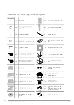
Page 3: ...R L16P SIDE PROFILE 16 MM CL16 CLIP ALU 16 MM CLLX SIDE CLIP 16 MM CLSB BASE SCREWABLE CLIP FROM 7 UP TO 16 MM CLST TOP SCREWABLE CLIP CLSL TOP SCREWABLE SIDECLIP PX POST 110 141 FOR GUTTER GX PGDX PO...

Page 4: ...IECE GUTTER FOR GX GLX GRSX END PIECE GUTTER FOR GX GR LOGO LOGO CLIMALUX FOR END PIECE GUTTER GDSX END PIECE FOR CROSS BEAM GDX MSX END PIECE WALL PROFILE FOR MX 909 CONNECTING PINS LGDX FIXING PROFI...

Page 5: ...ted as a claim Terms conditions and guarantee The guarantee is void when the installation instructions provided below are not followed Not following the instructions and or using other parts may have...

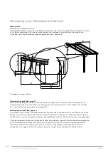
Page 6: ...m for a Climalux For a construction with eave please consult page 22 Determine the width B fig 2 page 7 The width B of the Climalux is the distance between the outer side of the side rafters If the Cl...

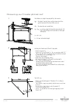
Page 7: ...e slid through the slotted holes in order to position the base plate properly The U for the base plate can be moved 20 mm either way to allow proper adjustment The 3 4 5 rule Determine the auxiliary p...

Page 8: ...the walls Make a slot in the walls against which the conservatory roof is to be installed Install a lead slab or zinc flashing Height first joint above Hm h and max 60 mm above the wall profile LED l...

Page 9: ...mm sheet must have a clearance lengthwise of 1 5 cm u Never block the sheet lengthwise or widthwise Always ensure sufficient clearance u Never stick the sheet using silicone even when it does not dam...

Page 10: ...lating struc ture in the sheet are sensitive to foot knee and other impressions at the surface Please take enough precau tions during transport and installa tion Impressions in the sheet are not cover...

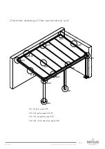
Page 11: ...ns_Skylux_Climalux Overview drawing of the conservatory roof A10 A11 posts page 13 29 A20 A23 gutters page 14 18 29 A30 A33 wall profiles page 19 29 A40 A42 rafters side rafters page 20 28 A10 A11 A20...

Page 12: ...E_MH_Mounting_instructions_Skylux_Climalux 01 11 2017 12 36 Climalux Installation tips...

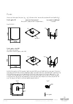
Page 13: ...rew set fig B for the corner posts Determine the position of the PV base plates as indicated on page 7 and anchor these on a solid foundation in concrete using the suitable fixing accessories not supp...

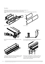
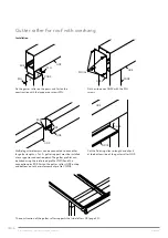
Page 14: ...be installed between two walls The 5 mm clearance on each side is required for the installation of the slide ends Pre drilling is required to install the U brackets if the gutter rafter is reinforced...

Page 15: ...Use a 80 mm circular drill not supplied Slide in the reinforcement profile V822 optional Installation of the U bracket PU Use the post caliber for the correct positioning The reinforcement profile V8...

Page 16: ...909 A raised profile GR can be installed on the GX gutter Position the side gutter slide ends first and subsequently fasten the GR profile on to the gutter every 500 mm 500 GR Install the water outlet...

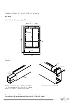
Page 17: ...14105 is not supplied It can be bought at any local hardware store We recommend treating the reinforcement profiles with an anti corrosion product 117 190 100 140 GDX GDCX V14105 Installation of the U...

Page 18: ...d screws ZSG Multiple gutter elements can be connected to each other for gutter lengths 7 m A gutter support must be installed at every gutter connection point The gutter profiles can be linked using...

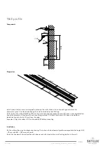
Page 19: ...at the top indication line with a diameter in function of the chosen fixing material Drill also a hole every 500 mm in the bottom indication line and start at 30 mm from the edge Important Slight the...

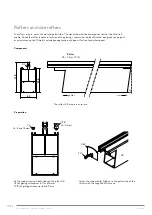
Page 20: ...raphs on page 31 or calculate using the Climafast calculation application at disposal for free for professionals Components Rafter DX C3 or CY10 The rafters DX are pre cut to size Preparation Fix the...

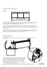
Page 21: ...lastics can be found on page 9 10 Divide the total width in equal parts of maximum 750 mm for glass The glazing quantity is determined as following B 60 mm 750 rounded off upwards The width of the gla...

Page 22: ...he rafter DX rests on the gutter rafter GDX at the gutter side Every rafter is fastened with 2 fixing profiles LGDX and ZSG screws Every rafter is fastened on to the wall side with 1 lacquered ZSG scr...

Page 23: ...Climalux Spacers Preparation spacers AX Fix a sealant C3 8 11 and 16 mm or CY10 8 9 mm on every spacer Installation spacers AX A spacer AX is clipsed between the rafter profiles at the gutter and wall...

Page 24: ...protected side of the sheet is always upwards All useful information for the processing and installation of glazing plastics can be found on page 9 10 Apply a silicone sealant that does not affect pla...

Page 25: ...are 3 positions for the clips Position 1 for glass 44 2 thickness 8 9 mm Position 2 for glass 55 2 thickness 10 11 mm Position 3 for 16 mm synthetic sheets The clips are fastened manually using a rubb...

Page 26: ...nds Fasten the CLSB to the rafter DX using ZSB screws Fasten perpendicularly and use a slight torque to ensure the screw head is pressed flat against the CLSB The CLST clips must be fastened manually...

Page 27: ...L16P profile against the outside against the rafter If you work with VRIJSTAAND or against the wall fasten the L16P profile every metre laterally against the rafter with ZSG or against the wall CLIP F...

Page 28: ...pressed flat against the CLSB Cut the CLLX CLSL profile obliquely in accordance with the roof slope x at the wall side To determine the length of the CLLX CLSL profile measure the distance to the stop...

Page 29: ...red screws ZSG We recommend to pre drill with 3 4 mm to avoid lacquer damage A frontal UGS water outlet is required to ensure that the water can flow outside when the water drainage is obstructed if t...

Page 30: ...p of each other A possible bending of the gutter profile above the sliding doors should therefore be taken into account When the selected gutter support cannot be installed where a certain span or loa...

Page 31: ...to the snow and wind load Practical example The axis distance AX between the rafters is 1000 mm for plastic sheets with a width of 980 mm The depth D of the roof is 3500 mm Determine the point on the...

Page 32: ...options Either you select the gutter GX with reinforcement V822 which allows a free span of 4100 mm Or you select a gutter rafter GX for maximum span of 3645 mm You then have to install an extra post...

Page 33: ...d is 500 N m 50 kg m The glass weighs 25 kg m ca 250 N m The total weight is 750 N m Determine the point in the 750 N m 1 300 graph and select a gutter support above this point The graph now has two o...

Page 34: ...former per LED strip of maximum 7 meters Pull the extenstion cable 6 m through the lateral rafter of the wall profile to the gutter The transformer is placed in the wall profile for which there is som...

Page 35: ...op profile 7 mm CY10 ZSB CY10 S16X 8 mm CY10 ZSB CY10 S16X 9 mm CY10 ZSB CY10 S16X 10 mm S16X 11 mm S16X 12 mm ZSG S16X 13 mm ZSG S16X 14 mm ZSG S16X 15 mm ZSB ZSG S16X 16 mm ZSB S16X Key ideal soluti...

Page 36: ...017 ONLY USE ORIGINAL PARTS DELIVERED BY SKYLUX EVERY GUARANTEE IS CANCELLED IF NON ORIGINAL PARTS ARE USED SKYLUX IS A REGISTERED BRAND OF SKYLUX SPINNERIJSTRAAT 100 B 8530 STASEGEM T 32 0 56 20 00 0...

Reviews: