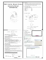
Multi-function Network Camera
Instruction Manual
DEFENDER 360
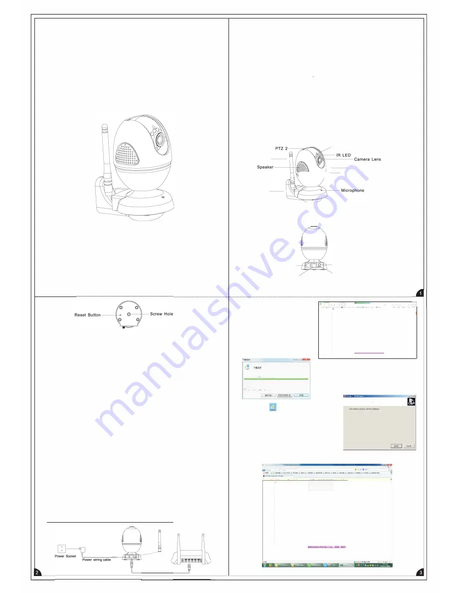
The Bottom Sketch
IR LEDs Distance: 3-5m
LED Status Light: RED ON-ARM GREEN ON-DISARM
BLUE ON-HOME ARM (Be triggered no alarm)
PTZ 1.Auto turn right or left in arm status
PTZ2.Auto turn up or down in arm status
TF Card Port. Backup port
Reset Button. Factory reset setting, using the thimble objects to click the small button.
4. Technical Parameter
Operating System, Ebedded Linux
User Interface: IE Brower, Onvif Client, Cms Client, Mobile Client
Video Formal: Main Stream: 960P/720P/D1 25fps Sub-stream: D1 /CIF 25fps
Audio Formal: G711A Support dual way voice, built in Mic and Speaker.
Ethernet Port, 1 0M/1 00M adaptive network interface. Wifi port
Backup Interface, TF Card, Max support 128G (32G above need to config from
the weblE and format the SD card)
Protocol: Meian Protocol, Meian P2P Protocol, Onvif Protocol
Power, DC12V input PS/2
5. Network Connection
5. 1 Wired Cable Connection
Make the wifi antenna connected to the GSM antenna pedestal and make the camera
connect to the power, through the Rj45 ethernet port connect to the Router with the wired
cable. The computer and camera network connection are on the same Router.
5. 2 WIFI Connection
Completed above 5.1 config. And login the weblE and set the WIFl(?.1.2 set wifi)
Then disconnecting the network wiring cable to the Router.
5. 3 GRPS Connection
The camera and Fortune-1 as Combo to use, If without the wifi and internet connection.
The camera will en bale the Gprs function and report the data to the CMS. CMS Connection:
Insert the SIM card to the Fortune GSM slot and enter into the weblE to set network( please
refer to instruction manual 8)
Attention: Router.IP camera and Computer with similar segments.
Network wiring cable
1. Introduction
The network camera is integrating the traditional camera and network video server
embedded into an digital monitoring system. Based on an embedded Linux operating
system. And adopts Hi3518C hardware platform with high efficient and low volume.
The system has high performance, good stability and reliability.
2. Open Package Checking
After opening the package, please confirm whether the system are in good condition
and verify if or parts are completed
Camera Bracket
Antenna
Screw
Green Expansion
Screw
Supply Cord
3. Appearance Introduce
Antenna- - -
----<
Bracket - - -
----<
1 Set
1 PC
1 PC
4 PCS
4 PCS
1 PC
Photo Resistor
f--- - -
PTZ 1
��
;;;;;;;
��r- -
LED status light
The Overall Schematic
Power Port
Rj45 Ethernet Port
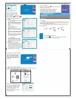
6. IP Camera Login
6.1 Login IE
The Back Sketch
Login the default IP address
http:// 192. 168. 1. 52 from the
weblE and config.
click up the bottom of the green
color character, and download the web
plugin to the computer then saved
EAVSOCX.exe
(
*
�
192
.
168.2
.
232
)
21-ft
2.CK™BC.SJii I t!))
l=
ffl!
-
C.
\
U
3en
\A
da
1
n
13t.
n
,t
o
r
\
Des
k
t
o
p
\
!
A
VSOC
l
.
,x,
fii':iclll·
2 OCWB/t!l
"[�Ulfilli;l;l!ill]
GSM Antenna Pedestal
TF Card Port
..........
,.,
...
..,.
,
Re;a
dy
to
l
n
s
ta
l
0
•
..
Sf'�
I
S
<'IOW
N!ad
y
tob@oi,l
�
l'/
�
on
your
ccmp.ite"
,
Find the Icon
�
Right-click to run as the Admin.
popup the window and click the install.
Note please close all the browsers before installing
the control.
Please login the default IP address http:
192.168.1.52 from the weblE again. And click to the
run the add-in as below photo.
d
OVll:
w.t,
•pp;.,......,....._
:-:::eiil) -
<)
�
•
:vl
lt'.il'!l!l.&I .tarn •
11i
1
M)
,.,_,,
•
@
•
'
•
X
.
1§1.161.l.2.12
i
�III
Jl!
,i
l'j
.,(
'f'.�
11;.l!!,
·
r
ooo.
-�
0:-&·�
11:
f:i
■
f
lll
-rcoo,-
�
,.
�
�
�
��
-"-"'
·
---
""
-
·
-
..
_
;i;a..
_______
_
�Ci;rn;IUtti:J(AJ
1',"-1!"1\!i(W)i
iU!t'.\!R&(ll


