background image

www.skyrc.com

- 07 -

BATTERY CHECKER

Connect the balance lead to ‘VOLT PORT’
Press ‘ENTER’ to enter main function screen
Press ‘ENTER’ to select BATTERY CHECKER function
Press ‘MODE’ to select battery type
Press ‘ENTER’ to confirm battery type

L i P o - 6 S   2 3 . 1 5 9 V
1 ) 3 . 8 4 7   2 ) 3 . 8 4 7
3 ) 3 . 8 5 2   4 ) 3 . 8 5 9
5 ) 3 . 8 7 7   6 ) 3 . 8 7 8
7 ) 0           8 ) 0
5 7 %   E                     F
6 9 %   X                     0
3 . 8 8 - 3 . 8 5 = 0 . 0 3 1

Remaining amount fuel gauge

The remaining amount gauge gives you a graphical bar graph display 
of the status of the battery by graph and the balance of the cells by 
graph. When the battery is fully charged the graph extends to “F” on 
the right hand side of the LCD. As in the example you can see that the 
battery is about 50% used.  There are times when differences occur 
between the remaining amount and the actual remaining amount. 
These differences can be associated with the quality and use of the 
battery and its cells. A battery that has always been charged with a 
reputable balancer is likely to reproduce accurate readings on the 
i-Meter.  A battery that has had a hard life full discharge and recharge 
with no balance charging is more likely to have discrepancies between 
actual and shown results.

Cell balance gauge

The Cell balance gauge measures the difference between all cells that 
are connected to the i-Meter.

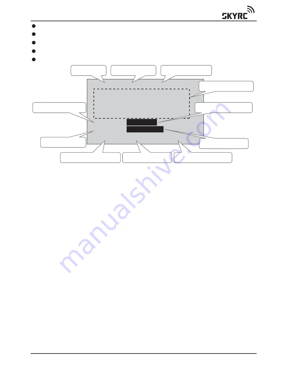
Battery Type

The Highest Cell Voltage

Remaining Amount %

Balance Status %

Individual Cell Voltage

Cell Balance Gauge

Lowest Cell Voltage

Cell Voltage Differential

Number of Cells

Serial Pack Voltage

Remaining Volts Gauge

Serial voltage

Pack voltage of the whole battery (total voltage of all cells) is indicated

The number of serial cells

The total number of cells in the battery pack is indicated (6S as indicated 
in the picture 6 serial cells). This is the same as the cell quantity. 

Summary of Contents for i-meter

Page 1: ...INSTRUCTION MANUAL Multimeter 7 in 1 www skyrc com 01...

Page 2: ...fire burns and personal injury The user must be familiar with the relevant methods procedures and connection components before using or making any connection High power electrical systems pose dangers...

Page 3: ...gned with ease of use as a prime objective This Instruction Manual describes the scope of i Meter and how to make it work for you Input Voltage Port LCD Display Dot Matrix 128 64 Connector to Temperat...

Page 4: ...ES 1 Battery Checker 2 Battery Internal Resistance 3 Watt Meter 4 Servo Tester 5 Optical Tachometer 6 Temperature Gauge 7 Thrust Calculator 1 Input Cable 2 Battery Internal Resistance Cable 3 i Meter...

Page 5: ...E T H R U S T C A L C S E T U P B A T T E R Y C H E C K E R I N T R E S I S T A N C E W A T T M E T E R S E R V O T E S T E R T A C H O M E T E R R P M T E M P E R A T U R E T H R U S T C A L C S E T...

Page 6: ...kes it possible to determine and verify the detailed state of the Lithium battery A balanced battery provides a safer environment when flying If you know that your cell balance is out you can address...

Page 7: ...ing amount These differences can be associated with the quality and use of the battery and its cells A battery that has always been charged with a reputable balancer is likely to reproduce accurate re...

Page 8: ...satisfactory cell balance then a cell balancer should be applied to the pack before use If the cell balance indication is low after the battery has been used this can be normal and charging should oc...

Page 9: ...ctance of which all contribute to the measured internal resistance Internal resistance can vary considerably even within the same cell this makes the task of determining the internal resistance a lot...

Page 10: ...r is lost during acrobatics or extreme conditions i Meter is activated when the battery is connected to the unit Press MODE to select WATT METER function Press ENTER to confirm selection PRECAUTIONS 1...

Page 11: ...and accumulates the charge Ah while the motor is running With a battery charger on the SOURCE side and battery pack on the LOAD side the meter shows the charging current into the battery the voltage a...

Page 12: ...your receiver The servo tester will put out a signal just like the signals normally sent by your receiver to the servos or ESC The dial knob on the servo tester will change the signal just like movin...

Page 13: ...tart RPM measurement To use the Servo Tester to operate an ESC and motor Connecting a battery to the i Meter volt port Another plug connected to the Servo Tester is the plug from the ESC that normally...

Page 14: ...ning move the optical sensor to about 10 20 cm from the propellers taking all due care Small propellers may require closer positioning The number of propeller blades should also be set Wrong setting w...

Page 15: ...e knowledge about your plane and the power characteristics to make your first flight less challenging and safe after all you may have other flight characteristics to deal with This should help you to...

Page 16: ...rational defects which are present at the time of purchase During that period we will repair or replace free of service charge for products deemed defective due to those causes SPECIFICATIONS ARE SUBJ...

Reviews: