SkyTrac Systems Ltd.
Document Rev. 01.020
DOC0334
Page 25 of 49
Restricted Proprietary and Confidential Information
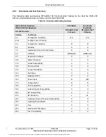
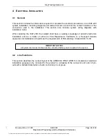
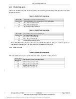
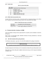
4.2.1 ITRAY-200R Pin-out
Note:
In the following figures, Bay B refers to the upper bay connector (with 106 pins), and Bay A
refers to the lower bay connector (with 30 pins).
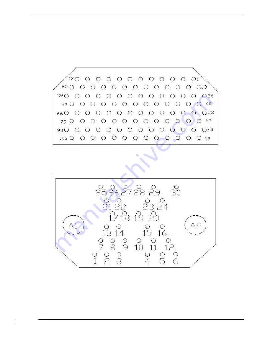
The following figures illustrate the ARINC 404 pin callouts using drawings, pin names, and pin
descriptions.
Figure 3
— ARINC404 Bay B: 106 pin-out drawing
Figure 4
— ARINC404 Bay A: 30 pin-out drawing
The document reference is online, please check the correspondence between the online documentation and the printed version.

