background image


 29

SURGICAL TABLE

6700B  HERCULES

OPERATORS MANUAL

REV 7/05

Summary of Contents for 6700B HERCULES

Page 1: ...29 SURGICAL TABLE 6700B HERCULES OPERATORS MANUAL REV 7 05...

Page 2: ......

Page 3: ...27 MODEL 6700B REV 7 05 Although current at the time of publication SKYTRON s policy of continuous development makes this manual subject to change without notice...

Page 4: ...tice of the defect within such period and complies with all other terms of this warranty then SKY TRON or its authorized service agent shall repair or replace the defective product or part thereof at...

Page 5: ...Operation 11 2 4 Automatic Shut Off 12 2 5 Charging the Battery 12 2 6 Positioning Functions 13 a Floor Lock Brake system 13 b Trendelenburg 14 c Lateral Tilt 14 d Back Section 15 e Elevation 15 f Le...

Page 6: ...SED ONLY IN SPECIFIED ENVIRONMENTAL CONDITIONS IPX4 V TEMPERATURE 15 30 C 60 85 F ENCLOSURE CLASS VOLTAGE RATING OF THE UNIT A AMPERAGE RATING OF THE UNIT HZ FREQUENCY OF THE UNIT ATTENTION CONSULT MA...

Page 7: ...amps 15 feet w hospital grade connector removable 12 1 2 19 1 4 23 24 1 4 14 1 2 19 3 4 5 3 4 3 76 TOP VIEW 90 60 14 1 2 36 SIDE VIEW 8 1 2 5 3 4 19 21 3 4 44 MAX 23 MIN END VIEW ENTELA CERTIFIED TO...

Page 8: ...patient safely Although the thick pads and sheets substantially protect the patient pinch points located at the joints of the top section should always be considered BE SURE THAT THE ARMS HANDS AND FI...

Page 9: ...unds NOTE Topreventtabledamage asafetyinter lock limits Trendelenburg positioning to 20 iflateraltiltpositioningexceeds20 An audible alarm will sound WARNING To maximize patient safety utilize properr...

Page 10: ...rthe power cord end of the base WARNING Always lock the table top in position after rotation DO NOT rotate the top with an unevenly distributed patient weight load as instability may result NOTE To pr...

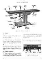
Page 11: ...faces may cause distortion of table tops WARNING MakesuretheTOPROTATIONLOCK HANDLE is tightened and the brakes are set before transferring the patient Exercise caution with the table top rotated90 tot...

Page 12: ...lift return to level beach chair and the floor lock brake sys tem Manual controls are provided for head section posi tioning table top rotation emergency brake re lease back section removal and leg s...

Page 13: ...r Lock Brake System The floor lock brake system consists of four self leveling hydraulic brake cylinders which raise and support the table base off from the casters Press the TABLE UP button on the pe...

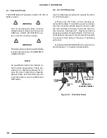
Page 14: ...f safety SECTION II OPERATION Figure 2 1 Electrical Panel 2 2 AC 120V Operation Use the following procedures to operate the table on 120 VAC power a Make sure the Power cord is securely at tached to t...

Page 15: ...buttons and the red BATTERY indicator light located in the upper right corner of the pendant control will illumi nate c The table is now ready for BATTERY opera tion d To extend the battery charge lif...

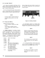
Page 16: ...utton on the pendant control the pendant control buttons and the red indicator light will illuminate NOTE Turning the Main Power Switch ON will change the table operation to 120 VAC power 2 5 Charging...

Page 17: ...BRAKE LOCK BRAKE UNLOCK AC120V POWER ON INDICATOR LIGHT GREEN TABLE UP BRAKE LOCK LATERAL TILT LEFT BACK UP LEG UP FLEX KIDNEY LIFT UP RETURN TO LEVEL LATERAL TILT RIGHT BACK DOWN TABLE DOWN LEG DOWN...

Page 18: ...during ex treme lateral tilt positioning 30 30 LATERAL TILT LEFT LATERAL TILT RIGHT b Trendelenburg To place the table in a Trendelenburg head down position press the TREND button figure 2 6 To place...

Page 19: ...e table top will go down to a minimum height of 23 WARNING The Leg section may hit the table base or the floor if both the leg and elevation systems are placed in their full down position d Back Secti...

Page 20: ...ety interlock prevents the kidney lift from going up if the back section is raised above horizontal An audible alarm will sound Figure 2 13 Return To Level j Beach Chair To place the top in the beach...

Page 21: ...UP BRAKE LOCK TREND TILT LEFT BACK DOWN TABLE DOWN LEG DOWN KIDNEY DOWN Figure 2 16 Emergency Back Up Controls Figure 2 15 Emergency Controls Location b In the event of either a power failure or a pr...

Page 22: ...ergency Brake Release NOTE The Emergency Brake Release Valve must be closed and tightened clock wise before activating any function If the Emergency Brake Release Valve has been operated the UNLOCK bu...

Page 23: ...G LEVERS Figure 2 20 Leg Section Removal c To install the Leg Section press and hold the LEG UP button until the attachment pins com pletely stop Install the section on the pins Level the table top an...

Page 24: ...K HANDLE clockwise WARNING Always lock the table top in position after rotation DO NOT rotate the top with an unevenly distributed patient weight load as instability may result Figure 2 21 Top Rotatio...

Page 25: ...mit weight capacities Check with your SKYTRON representative WARNING Consult manufacturer s instructions when using high frequency surgical equipment cardiacdefibrillatorandcar diac defibrillator moni...

Page 26: ...22 Upper Body Imaging Lower Body Imaging 6700B HERCULES General Purpose Patient Positioning Guidelines Neuro neck Neuro lumbar Ophthalmic ENT Nephrectomy Lap Nissen Urology...

Page 27: ...23 Shoulder Arthroscopy Neuro head Cysto GYN Cardiovascular Hip Revision Cardiovascular Abdominal Gall Bladder 6700B HERCULES Bariatric Recommended Patient Positioning Guidelines...

Page 28: ...ing fluid Using a clean dry lint free cloth wipe the pads to remove all moisture Repeat the steps to clean the bottom of the each pad 3 1 Preventive Maintenance The following preventive maintenance ch...

Page 29: ...ant control and cord Use a clean cloth dampened with water to remove cleaning solution Use another clean damp cloth to remove any remaining residue Install pendant control on side rail for storage whe...

Page 30: ......

Page 31: ......

Page 32: ...28 500036thStreetS E GrandRapids MI 49512 1 800 SKYTRONor1 616 957 0500 FAX1 616 957 5053...

Reviews: