background image

Page 12

6701 OPERATOR • REV2

2-1.  Electrical Power

The 6701 table will operate on either 120 VAC or 
battery power. 

WARNING

Prior  to  operating  the  table,  observe 
all table caution labels and review the 
SPECIAL USER ATTENTION section 
in the front of this manual.

WARNING

Possible explosion hazard exists if table 
is used in the presence of FLAMMABLE 
ANESTHETICS.

NOTE

An  equalization  terminal  is  located 
under  the  main  power  panel.  This  is 
provided  as  an  alternate  pathway  to 
reduce the risk of static shock hazards. 
Always follow recommended grounding 
procedures to ensure pattient and staff 
safety.


2-2.  AC 120V Operation 

Use the following procedures to operate the table 
on 120 VAC power.

 
  a.

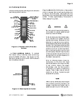
 Make sure the Power cord is securely attached 

to  the  table. To  install  the  power  cord,  align  the 
cord connector with the base connector, insert the 
cord and twist clockwise to lock the cord into the 
connector.  See figure 2-1.  Plug the cord into a 
properly grounded, Hospital Grade, 120 VAC outlet.  
Make sure the power cord is routed to the outlet 
to  prevent  it  from  being  in  the  way  of  operating 
personnel.

 SECTION II OPERATION

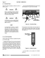
Figure 2-1.  Electrical Panel

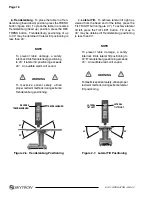
The  pendant  control  buttons  and  the  green  AC 
120V, POWER indicator light located in the upper 
right corner of the pendant control will illuminate.  
See figure 2-2.

Figure 2-2.  Pendant Control


c.

  The  table  is  now  ready  for  120VAC 

operation.  

  b.

 Activate the POWER SWITCH located on the 

electrical panel.  The switch will illuminate.

MAIN POWER

SWITCH

TWIST TO

LOCK

FOOT CONTROL

CONNECTOR

BATTERY

INDICATOR

POWER

CORD

EQUALIZATION

GROUNDING TERMINAL

AC120V POWER ON

INDICATOR LIGHT

(GREEN)

Summary of Contents for 6701 hercules

Page 1: ...SURGICAL TABLE 6701 HERCULES OPERATORS MANUAL TEC D 0010 REV2 6 11...

Page 2: ......

Page 3: ...1 Electrical Power 12 2 2 AC 120V Operation 12 2 3 Battery Operation 13 2 4 Automatic Shut Off 13 2 5 Charging the Battery 14 2 6 Positioning Functions 15 a Floor Lock Brake system 15 b Trendelenburg...

Page 4: ...EXERCISE CAUTION WITH THE TABLE TOP ROTATED 90 TO THE BASE SINCE AN IMPROPERLY DISTRIBUTED PATIENT LOAD MAY CAUSE THE TABLE TO BE TIPPED OVER TABLE TOP WARNING Table Capacity Lift 1200 lbs Articulate...

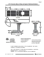
Page 5: ...ector removable 12 1 2 19 1 4 23 24 1 4 14 1 2 19 3 4 6 3 79 TOP VIEW 90 60 14 1 2 37 SIDE VIEW 8 1 2 5 3 4 19 22 41 MAX 23 MIN END VIEW UNIT TO BE USED ONLY IN SPECIFIED ENVIRONMENTAL CONDITIONS TEMP...

Page 6: ...for all personnel that may operate this table The maximum lifting capacity of the 6701 Herculestableis1 200poundsandthemaximum articulation weight capacity is 1 000 pounds When lifting or articulatin...

Page 7: ...connected to a wall outlet or disconnected NOTE Battery Operation must be turned OFF at the pendant control It can not be turned Off using the main power switch NOTE Turning the Main Power Switch ON w...

Page 8: ...o be unlocked the patient must be centered and evenly distributed on the table top i e supine or prone position withthetableloweredtoitslowestheight position The maximum patient weight shouldnotexceed...

Page 9: ...for proper orientation The Leg section cannot be installed on the Back section pins WARNING The Leg section may hit the table base or the floor if both the leg and elevation systems are placed in the...

Page 10: ...fromalackofpropermaintenance of this equipment NOTE Normal table top position is with the head and back section over the power cord end of the base WARNING Alwayslockthetabletopinpositionafter rotatio...

Page 11: ...cluding gloves masks and eye protection when cleaning the surgical table CAUTION Thoroughly read and follow the manu facturer s directions for all cleaning fluids DONOTusecleanerscontaining phenolics...

Page 12: ...lex kidney lift return to level beach chair and the floor lock brake system Manual controls are provided for head section positioning table top rotation emergency brake release back section removal an...

Page 13: ...on Buttons 1 4 Floor Lock Brake System The floor lock brake system consists of four self leveling hydraulic brake cylinders which raise and support the table base off from the casters Press the TABLE...

Page 14: ...securelyattached to the table To install the power cord align the cord connector with the base connector insert the cord and twist clockwise to lock the cord into the connector See figure 2 1 Plug the...

Page 15: ...ill illuminate c The table is now ready for BATTERY operation d To extend the battery charge life turn the BATTERY power OFF with the pendant control when the table is not going to be used NOTE Batter...

Page 16: ...e charge level turn off and light in sequence again NOTE When the red light starts to blink indicating low power in battery the table will operate for approximately 5 continuous minutes typically long...

Page 17: ...op i e supine or prone position withthetableloweredtoitslowestheight position The maximum patient weight shouldnotexceed500pounds Tabletop rotation must be in normal orientation that is the back secti...

Page 18: ...imize patient safety utilize properrestraintmethodsduringextreme Trendelenburg positioning c Lateral Tilt To achieve lateral tilt right as viewed from the head end of the table press the TILT RIGHT bu...

Page 19: ...t is not all the way down If the kidney lift is raised an audible alarm will sound when the BACK UP button is pressed NOTE Ifbacksectionisbelowhorizontal BACK UP function is limited to 800 pound patie...

Page 20: ...if both the leg and elevation systems are placed in their full down position g Flex Positioning To place the table top in a flex position from horizontal press the FLEX button figure 2 11 To return t...

Page 21: ...to level function Figure 2 14 Beach Chair Positioning j Beach Chair To place the top in the beach chairpositionfromalevelposition presstheBEACH CHAIR button figure 2 14 The back section will raise the...

Page 22: ...In case of a power failure or an electrical problem within the table the emergency brake release system can be used to move the table The control knob for this function is located on the side of the t...

Page 23: ...ve has been operated the BRAKE UNLOCKbuttononthependantcontrol will have to be pressed before brakes will lock again 2 9 Head Section a A quick release positioning bar located under and to the front o...

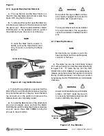
Page 24: ...ity may result Figure 2 21 Top Rotation 2 10 Leg and Back Section Removal a The Leg Section and the Back Section on the 6701 Hercules tables are both removable See figure 2 20 Leg Section shown b To r...

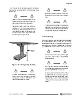
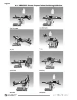
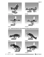
Page 25: ...te approved replacement 2 12 Positioning The use of certain optional accessories available from SKYTRON further extend the positioning capabilities of the 6701 Hercules Tables Refer to the following P...

Page 26: ...Page 24 6701 OPERATOR REV2 6701...

Page 27: ...Page 25 6701 OPERATOR REV2...

Page 28: ...and adjust if necessary 3 Pressurecheck withagauge thepressure relief valve 4 Check all mechanical adjustments and adjust as necessary 5 Check hydraulic fluid level 6 Lubricate the slider assembly 7 C...

Page 29: ...luids DONOTusecleanerscontaining phenolics Apply cleaning fluid liberally to top and sides of each pad and wipe with a clean lint free cloth Using a clean damp lint free cloth wipe the pads to remove...

Page 30: ...presentative To obtain SKYTRON authorized service or preventive maintenance contracts contact your nearest SKYTRON representative listed below Or contact SKYTRON 5085 Corporate Exchange Blvd S E Grand...

Page 31: ......

Page 32: ...5085 Corporate Exchange Blvd S E Grand Rapids MI 49512 1 616 656 2900 FAX 1 616 656 2906...

Reviews: