Page 20
6701 OPERATOR • REV2
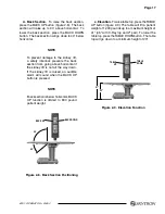
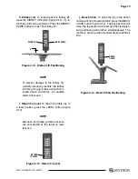
Figure 2-16. Emergency Back-Up Controls
CAUTION
The EMERGENCY BRAKE LOCK
switch does not activate the brake
system timer. The switch must be held
until the brakes are completely locked,
approximately 10 seconds.
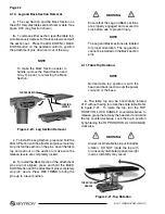
Figure 2-15. Emergency Controls Location
b.
In the event of either a power failure or a
problem with the hand-held pendant control, the
table can be operated using the emergency back-up
switches. Simply push the desired emergency
switch in the appropriate direction to operate the
table functions. See figure 2-16.
CAUTION
The Back Section/Kidney Lift safety
interlock is not operational when the
emergency back-up control switches
are used.
NOTE
The emergency back-up control
switches will function when the table is
operating on 120VAC power, battery
power, or turned off.
c.
Switches are provided for Trendelenburg,
lateral tilt, back section, elevation, leg section,
kidney down and brake lock. These switches are
spring-loaded so they return to the neutral or center
position when released.
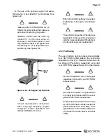
2-8. Emergency Brake Release.
In case of a power failure or an electrical problem
within the table, the emergency brake release
system can be used to move the table. The control
knob for this function is located on the side of the
table base and is identified by an EMERGENCY
BRAKE RELEASE label. Turn the knob clockwise
to release the brakes. See figure 2-17.
WARNING
•Do Not unlock brakes when patient is
on the table. An uneven patient weight
load may cause instability.
•If circumstances demand table brakes
to be unlocked, the patient must be
centered and evenly distributed on the
table top (i.e. supine or prone position)
with the table lowered to its lowest height
position. The maximum patient weight
should not exceed 500 pounds. Table top
rotation must be in normal orientation,
that is, the back section over the long
end of the table. Patient's head must be
on the head section. Head section must
be attached in its normal orientation to
the table's back section.
REV
TREND
TILT
RIGHT
BACK
UP
TABLE
UP
LEG
UP
BRAKE
LOCK
TREND
TILT
LEFT
BACK
DOWN
TABLE
DOWN
LEG
DOWN
KIDNEY
DOWN
FUNCTION CONTROL
ACCESS DOOR
2-7. Emergency Back-up Controls
a.
The emergency back-up control switches
are located under the access door on the service
access cover in the table base. See figure 2-15.
Summary of Contents for 6701 hercules
Page 1: ...SURGICAL TABLE 6701 HERCULES OPERATORS MANUAL TEC D 0010 REV2 6 11...
Page 2: ......
Page 26: ...Page 24 6701 OPERATOR REV2 6701...
Page 27: ...Page 25 6701 OPERATOR REV2...
Page 31: ......
Page 32: ...5085 Corporate Exchange Blvd S E Grand Rapids MI 49512 1 616 656 2900 FAX 1 616 656 2906...


