Page 8
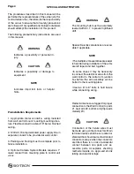
WARNING
The mounting hub must be accurately
leveled within 0.1° to prevent lighthead
drift.
2. Flatscreen Cables
a. Before installing the light radial arm, route all
video monitor cabling. If cabling is not available, a
pull cable should be routed to ease later installa-
tion.
b. A 30mm (1.25") raceway is provided to acco-
modate video cabling. Refer to minimally invasive
supply company for specific requirements prior to
installation. Always follow manufacturers specific
bend radii and state and local code requirements
when installing such cabling.
3. Light Radial Arm Assembly
NOTE
•The multiple arm assemblies are easier
to handle during installation if the arms
are left taped and tied together.
•In some cases it may be necessary
to connect the electrical wires from the
wall control to the radial arm junction
box before the arm assembly can be
bolted to the mounting plate.
•Use two 6" to 8" bolts to hold fixture
while connecting wiring.
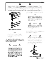
a. Install the Light Radial Arm Assembly(RAA)
into the receptacle on the Flatscreen Arm assembly
and secure with (6) M6 x 10 screws. Align the joint
shaft of the light radial arm to the hub assembly
and install (2) M8 x 30 Allen bolts.
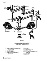
INSTALLATION PROCEDURE
The lighting fixture should be installed in the
following sequence:
1. Mounting Hub and Flatscreen Mount Arm
Assembly
2. Flatscreen Cables
3. Light Arm Assembly
4. Vertical Support Tubes/ Balance Mechanisms
5. Lightheads
6. Height Adjustable Arm
7. Flatscreen Mount
8. Wall Control
1. Mounting Structure
a. Check the strength and stability of the mount-
ing structure. It should be fabricated of steel and
welded or bolted to the structural ceiling. It should
be braced in a manner that will allow no twisting
or lateral motion. The 7/8" diameter support rods
should extend 2-1/4" below the finished ceiling for
LFS models and 1-1/4" below the finished ceil-
ing for LFSLFS models. See Mounting Structure
Guidelines in the back of this booklet. For Seismic
Applications please contact your local SKYTRON
distributors. Differences exist.
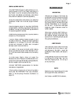
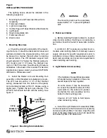
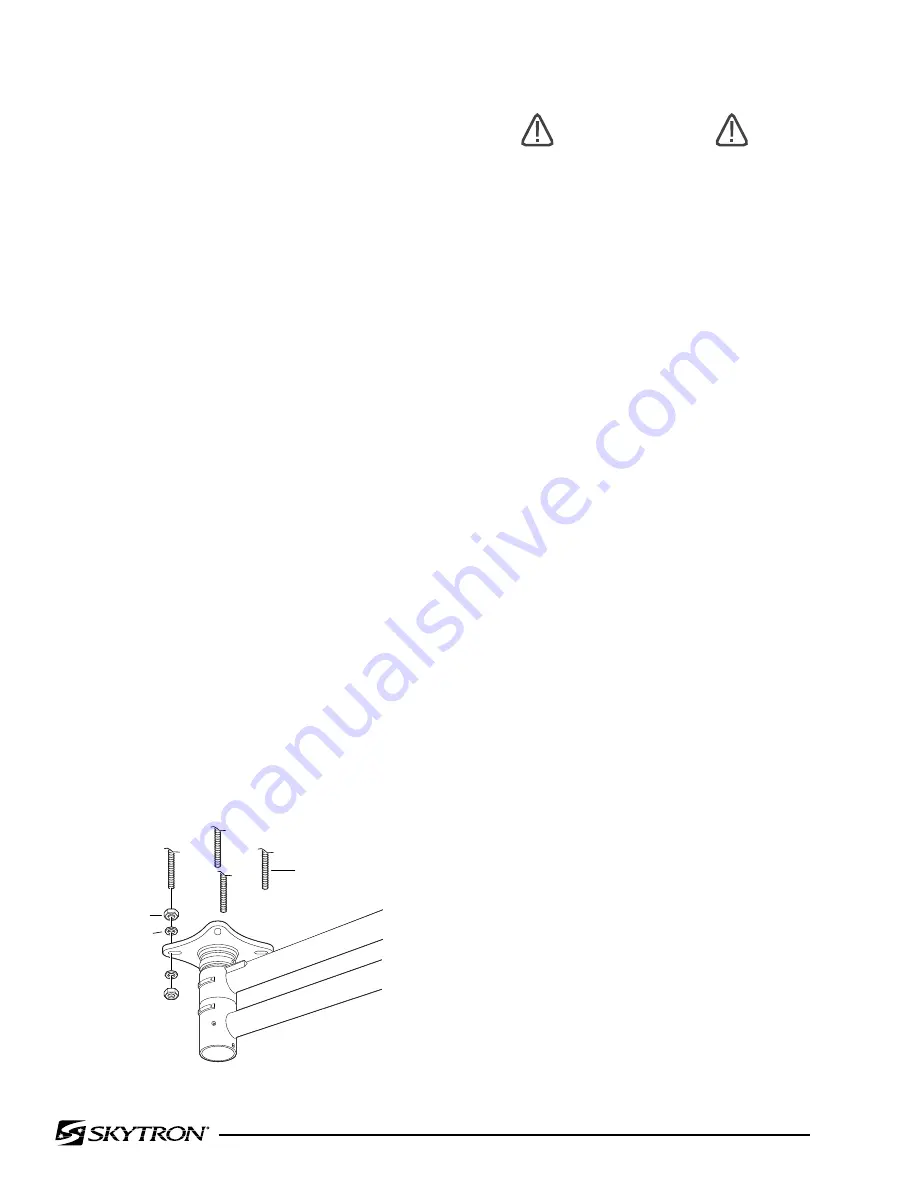
b. Install the Radial Arm and Mounting Hub
assembly on the threaded rods between jam nuts.
The LFS hub should be 1-1/4" off the finished
ceiling (measured from the bottom of the plate)
and accurately leveled, within 0.1 degree, using a
digital level. Tighten the jam nuts securely. The
LFSLFS hub should be flush with the ceiling. See
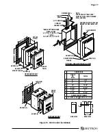
figure 2.
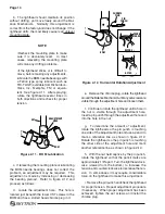
Figure 2. Mounting hub Installation
7/8"
THREADED ROD
(BY OTHERS)
NUT (8)
WASHER (8)
(BY OTHERS)
Summary of Contents for AURORA LED 5 4000K
Page 1: ...REV 9 08 INSTALLATION INSTRUCTIONS LED SERIES SURGICAL LIGHTS...
Page 18: ...Page 16...
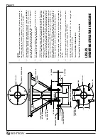
Page 20: ...Page 18...
Page 26: ...5085 Corporate Exchange Blvd S E Grand Rapids MI 49512 1 616 656 2900 FAX 1 616 656 2906...
Page 27: ...LED SERIES SURGICAL LIGHTS OPERATORS MANUAL TEC B 0002 REV0 1 09...
Page 47: ...5085 Corporate Exchange Blvd S E Grand Rapids MI 49512 616 656 2900 FAX 616 656 2906...
Page 48: ...PARTS CATALOG LED SERIES SURGICAL LIGHT TEC B 0009 REV3 3 10...
Page 54: ...Page 5 17 Stand Model Support Post Assembly page 40...
Page 65: ...Page 16 6 LED POD ASSEMBLY 57 010307 03mj 3 2 1 4 10 5 6 7 12 13 15 14 15 13 16 8 11 9...
Page 73: ...Page 24 10 LIGHTHEAD ASSEMBLY 1 2 6 7 8 9 11 13 14 12 10 5 3 4 57 031408 06mj...
Page 81: ...Page 32 13 TV LIGHTHEAD ASSEMBLY 1 3 4 5 6 7 8 9 10 11 12 15 17 18 13 16 14 2 5tv 081308 03...
Page 83: ...Page 34 14 WALL CONTROL ASSEMBLY 57 010307 04 1 5 6 9 10 3 2 7 8 4...
Page 85: ...Page 36 15 WALL CONTROL COMPONENTS 57 010307 05 1 2 3 4 5 6 12 13 14 7 8 9 10 11...
Page 91: ...5085 Corporate Exchange Blvd S E Grand Rapids MI 49512 616 656 2900 FAX 616 656 2906...
Page 92: ...MAINTENANCE MANUAL LED SERIES SURGICAL LIGHT 7 07...
Page 93: ......
Page 95: ...Page 2...
Page 110: ...5085 Corporate Exchange Blvd S E Grand Rapids MI 49512 616 656 2900 FAX 616 656 2906...
Page 111: ...REV 8 08 INSTALLATION INSTRUCTIONS LFS SERIES SURGICAL LIGHTS...
Page 133: ...Page 21...
Page 135: ...Page 23...
Page 138: ...5085 Corporate Exchange Blvd S E Grand Rapids MI 49512 1 616 656 2900 FAX 1 616 656 2906...
Page 139: ...LFS SERIES OWNERS MANUAL REV 6 08...
Page 140: ......
Page 142: ...Page 2...
Page 160: ...Page 20...
Page 170: ...5085 Corporate Exchange Blvd S E Grand Rapids MI 49512 1 616 656 2900 FAX 1 616 656 2906...
Page 171: ...INSTALLATION INSTRUCTIONS AUR SERIES SURGICAL LIGHTS TEC B 0006 REV1 8 09...
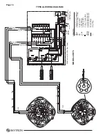
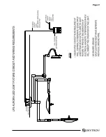
Page 188: ...Page 16 TYPICAL AURORA AUR LIGHT FIXTURE CONDUIT AND WIRING REQUIREMENTS...
Page 189: ...Page 17 TYPICAL WIRING DIAGRAM...
Page 190: ...Page 18 TYPICAL AURORA AURTV LIGHT FIXTURE CONDUIT AND WIRING REQUIREMENTS...
Page 191: ...Page 19 TYPICAL WIRING DIAGRAM...
Page 196: ...5085 Corporate Exchange Blvd S E Grand Rapids MI 49512 1 616 656 2900 FAX 1 616 656 2906...
Page 197: ...AUR SERIES SURGICAL LIGHTS OPERATORS MANUAL TEC B 0003 REV9 3 10...
Page 198: ......
Page 219: ......
Page 220: ...5085 Corporate Exchange Blvd S E Grand Rapids MI 49512 616 656 2900 FAX 616 656 2906...
Page 221: ...PARTS CATALOG AUR SERIES SURGICAL LIGHT TEC B 0004 REV6 6 10...
Page 222: ......
Page 274: ...5085 Corporate Exchange Blvd S E Grand Rapids MI 49512 616 656 2900 FAX 616 656 2906...
Page 275: ...AUR SERIES SURGICAL LIGHTS MAINTENANCE MANUAL TEC B 0007 REV1 1 10...
Page 276: ......
Page 278: ...Page 2...
Page 292: ...Page 16 TYPICAL WIRING DIAGRAM...
Page 293: ......
Page 294: ...5085 Corporate Exchange Blvd S E Grand Rapids MI 49512 616 656 2900 FAX 616 656 2906...
Page 295: ...TEC B 0008 REV3 3 10 OWNERS MANUAL HANDLE CAMERA SYSTEM...
Page 296: ......
Page 308: ...Page 12 PRECISION HD CAMERA SYSTEM...
Page 310: ...5085 Corporate Exchange Blvd S E Grand Rapids MI 49512 1 616 656 2900 FAX 1 616 656 2906...


