background image

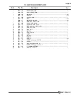
Page 40

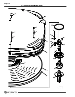
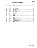
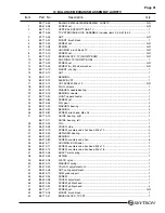
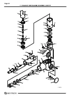
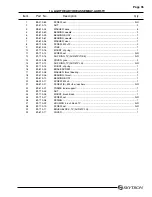
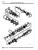
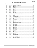
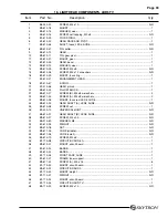
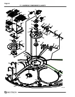
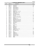
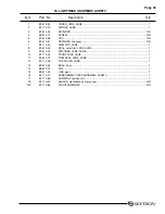
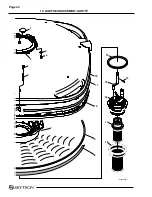
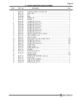
17. LIGHTHEAD COMPONENTS, AUR7TV

AUR-7TV LIGHTHEAD COMPONENTS

013009.08mj

28

1

2

4

3

3

5

3

6

3

7

8

9

15

14

11

10

12

13

29

27

26

25

23

21

30

31

10

32

33

32

24

22

18

3

20

34

16

19

17

35

39

38

37

36

33

40

33

1

41

33

44

33

43

42

Summary of Contents for AURORA LED 5 4000K

Page 1: ...REV 9 08 INSTALLATION INSTRUCTIONS LED SERIES SURGICAL LIGHTS...

Page 2: ...Distributed by SKYTRON 5085 Corporate Exchange Blvd S E Grand Rapids MI 49512 616 656 2900 www skytron us Manufactured by DKK Dai Ichi Shomei Co LTD Tokyo Japan...

Page 3: ...IVE AIR MOISTURE 10 85 NO CONDENSATE BUILD UP AIR PRESSURE 500 hPa 1060 hPa 14 in Hg 31 in Hg DURING USE FOR DRY LOCATIONS AMBIENT TEMPERATURE 15 30 C 60 85 F RELATIVE AIR MOISTURE 30 60 NON CONDENSIN...

Page 4: ...tion of the fixture wires must be made using crimp connectors Main terminal devices shall be so located or shielded that should a wire of a stranded conductor escape when the conductors are fit ted th...

Page 5: ...shall be employed throughout the fixture s wiring circuit where appli cable PROTECTIVE MEANS This fixture requires a properly circuit protected dedicated 120VAC 15 amp circuit An isolated power supply...

Page 6: ...odels require a 1 metal conduit from mounting plate to control unit J box SPECIAL USER ATTENTION WARNING The mounting plate must be accurately leveled within 0 1 to prevent lighthead drift NOTE Specia...

Page 7: ...rity of conductors NOTE Determine correct placement for each Balance Mechanism BOM Vertical Support Tube VST on the radial arm assembly The longest VST goes into the top radial arm WARNING Apply Blue...

Page 8: ...ION MODEL LED75 1 30 Diameter Lighthead 1 24 Diameter Lighthead MODEL LED755 1 30 Diameter Lighthead 2 24 Diameter Lightheads MODEL LED7 1 30 Diameter Lighthead MODEL LED5 1 24 Diameter Lighthead MODE...

Page 9: ...N surgical lights on existing mounting structures are available Contact your SKYTRON representative for special application details Additionalmaterialsrequiredforproperinstallation include Loc Tite co...

Page 10: ...mounting plate on the threaded rods between jam nuts The plate should normally be located 1 3 8 off the finished ceiling measured from the bottom of the plate and ac curately leveled within 0 1 degree...

Page 11: ...Arm wires are tagged for proper connection to the Wall Control top arm 1 next arm 2 bottom arm triple arm models 3 Figure 3 Radial Arm Installation Figure 2 Mounting Plate Installation b Observe wire...

Page 12: ...ghthead See figure 6 b Removethefour 4 screwsfromthelighthead support arm c Install the lighthead mounting collar onto the support arm and secure with the screws previously removed See figure 7 VST BO...

Page 13: ...echanism will be severely damaged and may result in bodily injury Figure 8 Above Horizontal Limit Stops Model LED5 Lighthead a To make it easier to install the lighthead locate the support arm of the...

Page 14: ...y and components VOIDING WARRANTY 5 Wall Control NOTE 3 4 metal conduit and minimum 12AWG wire 3 wires per lighthead is required between Wall Control and Fixture Separatededicatedconduitrequiredfor 12...

Page 15: ...Acting 0 1 2 3 4 5 0 1 2 3 4 5 TO LIGHTHEAD 2 TO LIGHTHEAD 1 NEUTRAL LINE GROUND 120VAC INPUT FROM FACILITY TO LIGHTHEAD 2 TO LIGHTHEAD 1 FIXTURE JUNCTION BOX R G W R G W R G W R G W R R G W W G R R G...

Page 16: ...ded conductorescapewhentheconductors are fitted there is no risk of accidental contact between live parts and ac cessible parts Acceptable sheilding methods include UL approved shrink tubing and elect...

Page 17: ...RONT EDGE OF BACK BOX MUST BE FLUSH WITH FINISHED WALL SURFACE 2 GROMMETS SCREW 4 RECESS MOUNT FLANGE ANCHOR 4 RECESSED MOUNT FRONT PANEL RECESS DEPTH A C B 3 20 00 0 HO UR INDICA TO R CO LO R TE MP E...

Page 18: ...Page 16...

Page 19: ...T SA L1 L6 A DCB 5 DCB 2 Radial Arm Assembly Vertical Support Tube Support Arm LED White Amber LED Crimp Connectors a drive circuit board a drive circuit board Brush Block Slip Ring 3 4 CONDUIT 12AWG...

Page 20: ...Page 18...

Page 21: ...TION 3 CONDUCTORS FIXTURE MOUNTED JUNCTION BOX 4 L x 4 W x 2 1 4 D COLOR TEMPERATURE INDICATOR 4 500K WHEN ILLUMINATED AC120V POWER SUPPLY DEDICATED 3 4 CONDUIT MAIN POWER SWITCH IMPORTANT 120 VAC iso...

Page 22: ...RON surgical light to be provided by Electrical Contractor All installations of SKYTRON surgical lights should be under the direct supervision of a SKYTRON representative All wiring to be in accordanc...

Page 23: ...light to be provided by Electrical Contractor All installations of SKYTRON surgical lights should be under the direct supervision of a SKYTRON representative All wiring to be in accordance with local...

Page 24: ...f SKYTRON surgical lights should be under the direct supervision of a SKYTRON representative All wiring to be in accordance with local codes and by a certified electrician CONTRACTOR HAS FINAL RESPONS...

Page 25: ...tainer to the sender without such an inspection may prevent filing a claim because it will divide the responsibility for damage and in many cases the transportation company will return the shipment to...

Page 26: ...5085 Corporate Exchange Blvd S E Grand Rapids MI 49512 1 616 656 2900 FAX 1 616 656 2906...

Page 27: ...LED SERIES SURGICAL LIGHTS OPERATORS MANUAL TEC B 0002 REV0 1 09...

Page 28: ...ration 10 Lighthead Positioning 12 Illumination Technique 14 Maintenance 18 Distributed by SKYTRON 5085 Corporate Exchange Blvd S E Grand Rapids MI 49512 616 656 2900 www skytron us Manufactured by DK...

Page 29: ...rradiance to Illuminance millwatts m2 per lux Total Irradiance watts m2 UV Energy watts m2 Chomaticity X Coordinates Y Shadow Dilution Percentage Remaining Illumination with one mask two masks tube tu...

Page 30: ...E IN ORIGINAL PACKAGING MATERIALS AMBIENT TEMPERATURE 10 60 C 14 140 F RELATIVE AIR MOISTURE 10 85 NO CONDENSATE BUILD UP AIR PRESSURE 500 hPa 1060 hPa 14 in Hg 31 in Hg DURING USE FOR DRY LOCATIONS A...

Page 31: ...B9 610 03 120V 120V 120V 1 2A 2 4A 3 6A 144W 288W 432W 60Hz 60Hz 60Hz 30V DC 30V DC 30V DC 2 8A 5 6A 8 4A 84W 168W 252W 2A 2A x 2 2A x 3 TIMELAG TIMELAG TIMELAG Manufactured for SKYTRON by DAI ICHI S...

Page 32: ...possibility of personal in jury CAUTION Indicates a possibility of damage to equipment NOTE Indicates important facts or helpful hints WARNING Be sure sterile handle is properly se cured before using...

Page 33: ...cleaning agents will cause damage to the fixture Avoid the use of cleaning solutions which contain high concentrations of alcohol ethelene glycol phenol iodophors or glutaraldehyde based disinfectanct...

Page 34: ...ED75 1 30 Diameter Lighthead 1 24 Diameter Lighthead MODEL LED755 1 30 Diameter Lighthead 2 24 Diameter Lightheads MODEL LED7 1 30 Diameter Lighthead MODEL LED5 1 24 Diameter Lighthead MODEL LED55 2 2...

Page 35: ...ntion Figure 1 Light Fixture Rotation Capabilities INTRODUCTION 360 PITCH 360 PITCH 360 360 ROLL 360 VERTICAL SUPPORT TUBE BALANCE MECHANISM 110 VERTICAL TRAVEL CEILING COVER 360 ROLL 360 The lights c...

Page 36: ...al arm by a vertical support tube provides the lighthead an additional continuous 360 rotation point The balance mechanism is an enclosed spring tension system This allows vertical move ment of the li...

Page 37: ...KNOBS STERILIZABLE FOCUS POSITIONING HANDLES Use the following instructions to operate the light fixture 1 Position the lightheads as required by grasp ing the lighthead positioning handles and movin...

Page 38: ...al light Figure 5 Center Focus Positioning Handle Installation 5 Adjust the focus by moving either the non sterile focus knob or the sterilized center focus handle until all of the light beams converg...

Page 39: ...uring procedure Position of surgical team Location of instrument trays or tables Location of IV stands X ray equipment and personnel Anesthesia equipment and personnel Angulation and size of surgical...

Page 40: ...patient Figure 7 Figure 8 Main Lighthead Radial Arm Positioning 5 With the radial arm in proper position rotate the lighthead to the desired position and install the sterile positioning focus handle R...

Page 41: ...hed by non sterile personnel Position the satellite light head depending on lighting needs to augment the larger lighthead ILLUMINATION TECHNIQUE Maximum illumination shadow reduction and pos sible ob...

Page 42: ...e for perineal procedures Lo cate the radial arm directly in line with the centerline of the table Once the surgeon has assumed a seated position the lighthead can be pulled down angled and adjusted t...

Page 43: ...ilting the lightheads will give a larger light beam angle See figure 15 Final positioning and focus adjustments can be done by the surgeon using the sterile focus positioning handles Focus con trols s...

Page 44: ...g at the bottom of the cavity may cause more shadow problems The focal point for the light beams should be above the bottom of the cavity See figure 17 Figure 17 Beyond the focal point the light beams...

Page 45: ...SKYTRON surgical lighting system the following preventive maintenance procedures are recommended NOTE All repairs should be made using only authorized SKYTRON replacement parts Daily Maintenance Daily...

Page 46: ...ormance Maintenance must be performed by authorized trained maintenance personnel using SKYTRON authorized replacement parts and service tech niques Service instructions and parts are available from S...

Page 47: ...5085 Corporate Exchange Blvd S E Grand Rapids MI 49512 616 656 2900 FAX 616 656 2906...

Page 48: ...PARTS CATALOG LED SERIES SURGICAL LIGHT TEC B 0009 REV3 3 10...

Page 49: ...e of publication SKYTRON s policy of continuous development makes this manual subject to change without notice MODEL CAT NO SERIAL NO The lighthead Data Label located on center band of lighthead and w...

Page 50: ...Page 1 1 Radial Arm Assembly page 6 2 Balance Mechanism Assembly LED5 page 8 3 Balance Mechanism Assembly LED7 page 10 4 Lighthead Yoke Assembly Model LED5 page 12...

Page 51: ...Page 2 5 Lighthead Yoke Assembly Model LED7 page 14 6 LED Pod Assembly page 16 7 Focus Mechanism Assembly page 18 8 Lighthead Components LED5 page 20...

Page 52: ...Page 3 9 Lighthead Components LED7 page 22 10 Lighthead Assembly page 24 11 Lighthead Components LED5TV page 26 12 Lighthead Components LED7TV page 28 29...

Page 53: ...Page 4 13 TV Lighthead Assembly page 32 14 Wall Control Assembly page 34 15 Wall Control Components page 36 16 LED Stand Model Base Assembly page 38...

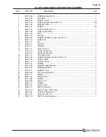
Page 54: ...Page 5 17 Stand Model Support Post Assembly page 40...

Page 55: ...Page 6 1 RADIAL ARM ASSEMBLY 1 4 3 5 6 7 2 9 24 23 22 21 10 13 8 20 19 18 14 15 16 8 12 25 11 17 57 031408 01mj 26...

Page 56: ...R 12 B2 310 05 BRUSH BLOCK AND COVER ASSEMBLY plastic A R B3 610 21 BRUSH BLOCK AND COVER ASSEMBLY TV A R 13 B2 210 19 BRAKE SCREW A R 14 B2 210 26 NUT retainer 1 15 B2 210 27 SET SCREW 1 16 B2 210 58...

Page 57: ...Page 8 2 BALANCE MECHANISM ASSEMBLY MODEL LED 5 5 010307 04mj 1 2 3 4 5 8 9 10 13 13 16 18 19 19 22 30 23 24 25 26 28 31 34 35 36 37 38 39 40 41 5 7 6 32 33 27 29 21 20 17 15 14 11 12 6 7 42 43...

Page 58: ...upper knuckle 1 16 B9 610 70 PIN 1 17 B9 210 82 SCREW set 1 18 B3 210 34 PIN pivot 2 19 B3 210 32 WASHER bearing 4 20 B3 210 33 BEARING 2 21 B9 210 81 SCREW allen M5 x 25 2 22 B3 610 15 GUIDE bearing...

Page 59: ...Page 10 3 BALANCE MECHANISM ASSEMBLY MODEL LED 7 7 010307 04mj 1 2 3 4 5 8 9 10 13 13 17 18 40 18 21 29 22 23 24 25 27 30 33 34 35 36 37 38 41 3 31 32 26 28 42 20 19 16 15 14 11 12 6 7 39...

Page 60: ...10 05 JOINT upper knuckle 1 16 B9 210 82 SCREW set 1 17 B3 210 34 PIN pivot 2 18 B3 210 32 WASHER bearing 4 19 B3 210 33 BEARING 2 20 B9 210 81 SCREW allen M5 x 25 2 21 B3 610 06 GUIDE bearing right 1...

Page 61: ...Page 12 4 LIGHTHEAD YOKE ASSEMBLY MODEL LED 5 1 8 2 3 9 10 11 11 10 12 13 14 13 6 18 23 22 24 19 4 15 17 16 16 21 20 3 1 9 8 4 5 6 7 5 010307 01mj...

Page 62: ...part of assembly 2 11 B1 220 08 COVER yoke 1 12 B1 610 03 BRAKE SCREW 1 13 B1 410 06 WASHER thrust bearing 2 14 B1 410 05 BEARING thrust 1 15 B4 230 11 SCREW M4 x 4 4 16 B4 210 09 SCREW allen M4 x 8...

Page 63: ...Page 14 5 LIGHTHEAD YOKE ASSEMBLY MODEL LED 7 33 16 17 19 20 31 31 32 19 21 23 30 29 12 26 24 22 1 2 3 4 11 28 25 27 6 18 7 010307 01mj 5 12 15 14 6 7 8 10 11 13 9...

Page 64: ...14 B9 410 14 SCREW set M4 x 8 cone point 1 15 B1 410 26 COVER yoke 1 16 B3 210 05 BRUSH BLOCK 1 B3 610 22 BRUSH BLOCK TV part of assembly 1 17 B1 610 03 BRAKE SCREW 1 18 B4 342 14 SCREW M3 x 12 2 19...

Page 65: ...Page 16 6 LED POD ASSEMBLY 57 010307 03mj 3 2 1 4 10 5 6 7 12 13 15 14 15 13 16 8 11 9...

Page 66: ...AINER A R 5 B9 610 47 PIN cotter 7 5 6 B9 610 45 SHAFT focus LED7 7 B9 610 46 SHAFT focus LED5 5 7 B4 020 22 NUT M4 7 5 8 B1 610 37 LINK focus 7 5 9 B9 610 19 SCREW M3 x 6 14 10 10 B9 610 44 RETAINER...

Page 67: ...Page 18 7 FOCUS MECHANISM ASSEMBLY 1 2 3 4 5 6 7 8 9 10 11 12 13 14 15 13 13 18 24 19 16 17 21 22 23 20 14 13 11 4 57 010307 02mj...

Page 68: ...COLLAR 1 11 B9 610 34 SCREW set A R 12 B9 610 39 GEAR SHAFT C 1 13 B9 610 28 SCREW set A R 14 B1 420 70 UNIVERSAL JOINT 1 15 B9 610 31 GEAR SHAFT B LED5 1 B9 610 32 GEAR SHAFT B LED7 1 16 B9 610 19 SC...

Page 69: ...Page 20 8 LIGHTHEAD COMPONENTS LED5 5 010307 03mj 1 2 3 4 5 6 7 8 13 18 12 24 9 10 11 13 14 21 25 26 27 28 14 14 29 14 14 15 16 17 19 20 23 22 30 32...

Page 70: ...2 B9 610 13 WASHER wear 1 13 B9 610 09 SCREW M4 x 8 6 14 B9 610 06 SCREW M4 x 12 w washers 15 15 B1 610 29 MOUNT focus ring 1 16 B9 510 18 NUT 2 17 B1 610 25 WEIGHT A R 18 B1 610 27 ENGAGEMENT HEAD 1...

Page 71: ...Page 22 9 LIGHTHEAD COMPONENTS LED7 6 7 010307 03mj 1 2 1 3 8 11 4 12 14 17 24 25 26 27 28 18 22 29 21 13 15 16 19 20 19 23 19 19 19 30 31 18 5 9 10 7 33...

Page 72: ...ACK AND PIVOT 1 12 B9 610 12 GEAR 1 13 B4 242 23 SCREW M4 x 12 2 14 B9 610 11 PIN gear pivot 1 15 B1 610 31 MOUNT gear 1 16 B1 610 30 GEAR bevel 1 17 B9 610 13 WASHER wear 1 18 B9 610 09 SCREW M4 x 8...

Page 73: ...Page 24 10 LIGHTHEAD ASSEMBLY 1 2 6 7 8 9 11 13 14 12 10 5 3 4 57 031408 06mj...

Page 74: ...7 B1 610 57 RETAINER top cover A R 8 B1 610 19 TRIM SEAL LED5 1 B1 610 18 TRIM SEAL LED7 1 9 B1 610 16 FRONT FACE LED5 1 B1 610 15 FRONT FACE LED7 1 10 B1 610 42 DIFFUSER LED5 1 B1 610 41 DIFFUSER LE...

Page 75: ...GHTHEAD COMPONENTS LED5TV 1 2 7 8 5 11 14 37 38 39 40 41 42 42 54 55 53 42 42 43 15 15 32 33 6 9 10 16 34 35 36 17 18 20 21 23 24 25 19 4 3 12 13 26 27 44 46 47 50 48 56 47 45 49 51 52 28 29 30 31 22...

Page 76: ...25 B1 410 57 E RING 1 26 B9 611 31 SCREW A M3 x 15 w washers 1 27 B1 421 06 CIRCUIT BOARD motor 1 28 B9 611 30 SPACER 1 29 B9 610 19 SCREW M3 x 6 1 30 B9 611 29 MOUNT circuit board 1 31 B9 610 06 SCR...

Page 77: ...D COMPONENTS LED7TV 7tv 081308 01 1 2 14 43 36 17 18 19 20 38 39 40 41 21 22 23 29 34 35 32 33 35 36 37 30 25 31 27 28 24 26 15 4 3 7 8 10 12 13 45 49 51 52 46 47 53 54 55 36 36 57 56 58 36 1 59 44 50...

Page 78: ...0 28 SCREW set A R 22 B9 610 24 GEAR SHAFT A 1 23 B9 611 24 SCREW A M4 x 8 w washers 2 24 B9 610 25 MOUNT focus rod LED7 1 25 B9 610 27 SCREW B M4 x 8 w washers 2 26 B9 610 23 PILLOW BLOCK 1 27 B1 410...

Page 79: ...PONENTS LED7TV continued 7tv 081308 01 1 2 14 43 36 17 18 19 20 38 39 40 41 21 22 23 29 34 35 32 33 35 36 37 30 25 31 27 28 24 26 15 4 3 7 8 10 12 13 45 49 51 52 46 47 53 54 55 36 36 57 56 58 36 1 59...

Page 80: ...continued 52 B9 611 29 MOUNT circuit board 1 53 B9 611 32 SCREW A M4 x 15 6 54 B1 610 24 BAND B 1 55 B1 610 23 BAND A 1 56 B9 610 78 SCREW M4 x 12 w washers A R 57 B1 610 20 FRAME inner support 1 58...

Page 81: ...Page 32 13 TV LIGHTHEAD ASSEMBLY 1 3 4 5 6 7 8 9 10 11 12 15 17 18 13 16 14 2 5tv 081308 03...

Page 82: ...0 43 SEAL outer trim LED7 1 9 B1 610 42 DIFFUSER LED5 1 B1 610 41 DIFFUSER LED7 1 10 B1 610 16 FRONT FACE LED5 1 B1 610 15 FRONT FACE LED7 1 11 B1 610 19 TRIM SEAL LED5 1 B1 610 18 TRIM SEAL LED7 1 12...

Page 83: ...Page 34 14 WALL CONTROL ASSEMBLY 57 010307 04 1 5 6 9 10 3 2 7 8 4...

Page 84: ...lectrical access 2 5 B9 610 53 HOUSING wall control single or dual 1 B9 610 54 HOUSING wall control triple 1 6 B9 610 55 PANEL wall control front LED7 or LED5 1 B9 610 56 PANEL wall control front LED7...

Page 85: ...Page 36 15 WALL CONTROL COMPONENTS 57 010307 05 1 2 3 4 5 6 12 13 14 7 8 9 10 11...

Page 86: ...cator 1 3 B9 610 70 SCREW 4 4 B9 610 60 SCREW A R 5 B9 610 61 PLATE power supply unit single or dual 1 B9 610 62 PLATE power supply unit triple 1 6 B9 610 63 POWER SUPPLY UNIT A R 7 B9 510 18 NUT lock...

Page 87: ...Page 38 16 LED STAND MODEL BASE ASSEMBLY 091807 01 1 2 3 4 5 6 7 13 14 15 18 18 18 34 18 29 28 23 19 20 17 18 22 24 25 27 26 16 21 8 9 11 12 10 30 30 30 31 32 33 32...

Page 88: ...4 pin 1 15 B9 610 82 CIRCUIT BOARD 20 000 hour indicator 1 16 B9 610 92 WIRE HARNESS 2 wire 1 17 B9 610 93 CIRCUIT BOARD 1 18 B9 610 94 SCREW w flat lock washer phillips M4 x 8 A R 19 B9 610 95 CONNE...

Page 89: ...Page 40 17 STAND MODEL SUPPORT POST ASSEMBLY 1 3 5 6 7 8 9 10 11 12 13 14 15 19 31 30 28 32 30 33 29 20 16 22 34 35 23 24 23 26 27 25 17 21 36 18 2 4 4 091807 02mj 7 7 7 7 4 37...

Page 90: ...16 B9 611 13 SHAFT balance 1 17 B4 341 21 GUIDE bearing left 1 B4 341 22 GUIDE bearing right 1 18 B9 611 14 HOUSING BOM 1 19 B4 342 56 SCREW allen countersunk M4 x 14 8 20 B4 341 06 COVER rubber 2 21...

Page 91: ...5085 Corporate Exchange Blvd S E Grand Rapids MI 49512 616 656 2900 FAX 616 656 2906...

Page 92: ...MAINTENANCE MANUAL LED SERIES SURGICAL LIGHT 7 07...

Page 93: ......

Page 94: ...ures 6 1 4 LED Module Changing 7 1 5 Focus Adjustment 8 SECTION II POSITIONING AXIS ADJUSTMENT 9 2 1 General 9 2 2 Lighthead Pitch Adjustment 10 2 3 Model 7 Lighthead Roll Adjustment 11 2 4 Model 5 Li...

Page 95: ...Page 2...

Page 96: ...rradiance to Illuminance millwatts m2 per lux Total Irradiance watts m2 UV Energy watts m2 Chomaticity X Coordinates Y Shadow Dilution Percentage Remaining Illumination with one mask two masks tube tu...

Page 97: ...OUS OPERATION TYPE B EQUIPMENT PERMISSIBLE ENVIRONMENTAL CONDITIONS DURING TRANSPORT AND STORAGE IN ORIGINAL PACKAGING MATERIALS AMBIENT TEMPERATURE 10 60 C 14 140 F RELATIVE AIR MOISTURE 10 85 NO CON...

Page 98: ...B9 610 03 120V 120V 120V 1 2A 2 4A 3 6A 144W 288W 432W 60Hz 60Hz 60Hz 30V DC 30V DC 30V DC 2 8A 5 6A 8 4A 84W 168W 252W 2A 2A x 2 2A x 3 TIMELAG TIMELAG TIMELAG Manufactured for SKYTRON by DAI ICHI S...

Page 99: ...rocedures from the adjustment sec tion of this manual Section 2 SECTION I MAINTENANCE 1 1 General To ensure proper operation and extend the life of your SKYTRON surgical lighting fixture the follow in...

Page 100: ...from the pad See figure 1 3 Figure 1 3 d Install new module in reverse order of re moval e Reset Change Indicator after changing LEDs using the following procedure 1 Turn off power to fixture 2 Remov...

Page 101: ...rew as needed to achieve proper alignment See figure 1 6 Figure 1 5 Figure 1 6 1 5 Focus Adjustment As part of normal Preventive Maintenance the lighthead focus adjustment should be checked If an adju...

Page 102: ...Horizontal Rotation paragraph 2 7 Figure 2 1 Fixture Rotation Axis 2 1 General As a part of normal preventive maintenance all fixture rotation axes adjustments should be checked and adjusted as neces...

Page 103: ...e top cover when adjustment is complete Figure 2 2 Lighthead Pitch b The lighthead should move freely yet main tain its position without drifting If an adjustment is required remove the top cover refe...

Page 104: ...ntil an allen set screw is visible through the adjustment hole and loosen the set screw Figure 2 5 Model 7 Roll Adjustment d Continue to rotate the yoke until a 5mm hole is visible through the hole In...

Page 105: ...odel 5 lighthead by moving it through its full 360 range of travel See figure 2 6 Figure 2 7 Model 5 Roll Adjustment d Continue to rotate the yoke until a 5mm hole is visible through the hole Insert a...

Page 106: ...orizontal rotation axis adjustment by moving the lighthead through its full range of travel around the Balance Mechanism See figure 2 10 Figure 2 10 Horizontal Rotation D Figure 2 8 Lighthead Vertical...

Page 107: ...the adjustment hole This hole is located just beneath the lower VST screws in the BOM and has a slotted head chrome plug in it BOM VST ADJUSTMENT HOLE e Remove the chrome plug rotate the lighthead ar...

Page 108: ...heck the horizontal rotation axis tension by moving the Radial Arms through their full range of travel around the center mounting hub Refer to figure 2 13 Figure 2 13 E Service A regular program of pr...

Page 109: ...1 L6 A DCB 5 DCB 2 Radial Arm Assembly Vertical Support Tube Support Arm LED White Amber LED Crimp Connectors a drive circuit board a drive circuit board Brush Block Slip Ring COLOR TEMPERATURE INDICA...

Page 110: ...5085 Corporate Exchange Blvd S E Grand Rapids MI 49512 616 656 2900 FAX 616 656 2906...

Page 111: ...REV 8 08 INSTALLATION INSTRUCTIONS LFS SERIES SURGICAL LIGHTS...

Page 112: ...Distributed by SKYTRON 5085 Corporate Exchange Blvd S E Grand Rapids MI 49512 616 656 2900 www skytron us Manufactured by DKK Dai Ichi Shomei Co LTD Tokyo Japan...

Page 113: ...eration of nearby equipment It may be necesssary to take mitigation measures such as re orienting or relocating the lighthead or shielding the location PERMISSIBLE ENVIRONMENTAL CONDITIONS DURING TRAN...

Page 114: ...tion of the fixture wires must be made using crimp connectors Main terminal devices shall be so located or shielded that should a wire of a stranded conductor escape when the conductors are fit ted th...

Page 115: ...shall be employed throughout the fixture s wiring circuit where appli cable PROTECTIVE MEANS This fixture requires a properly circuit protected dedicated 120VAC 15 amp circuit An isolated power supply...

Page 116: ...Models require a 1 metal conduit from mounting plate to control unit J box SPECIAL USER ATTENTION WARNING The mounting hub must be accurately leveled within 0 1 to prevent lighthead drift NOTE Special...

Page 117: ...NOTE 3 4 metal conduit and minimum 12AWG wire 3 wires per lighthead is required between Wall Control and Fixture Separatededicatedconduitrequiredfor 120VAC supply lines to wall control Allwiringtobein...

Page 118: ...3 Light Arm Assembly 4 Vertical Support Tubes Balance Mechanism Typical Installation Sequence Component Identification 7 8 THREADED ROD CEILING COVER LFS RAA LIGHT RAA VST BOM UPPER VST LOWER VST HEI...

Page 119: ...or Please consult flatscreen moni torinstructionsforspecificdetailsandrequirements Monitor weight cannot exceed 20 lbs Contact SKYTRON representative for Seismic calculations if applicable The mountin...

Page 120: ...ub assembly and install 2 M8 x 30 Allen bolts INSTALLATION PROCEDURE The lighting fixture should be installed in the following sequence 1 Mounting Hub and Flatscreen Mount Arm Assembly 2 Flatscreen Ca...

Page 121: ...top arm 1 next arm 2 bottom arm triple arm models 3 b Observe wire tags and color codes and con nect the electrical wires from the wall control to the radial arm junction box wires CAUTION Connection...

Page 122: ...y Figure 5 VST to RAA Installation c Insert the vertical support tube into the radial arm receptacle Observe any screw color codes apply Loc Tite to screw threads and secure the BOM VSTassemblywiththe...

Page 123: ...ht Adjustable Arm clockwise until it contacts the stop c Align Height Adjustable Arm in line with upper radial arm as shown in figure 10 Model LED5 Lighthead a To make it easier to install the lighthe...

Page 124: ...decrease tension Tighten set screw when adjustment is complete i For fine adjustment rotate the monitor down ward until the adjustment nut is visible on the ten sion spring assembly Using a pin punch...

Page 125: ...rovided See figure 17 Figure 16 8 Upper Flatscreen Radial Arm Stop Adjust ment The Flatscreen Radial Arm has a ball stop mecha nism that allows 340 of rotation in 30 increments Use the following proce...

Page 126: ...he front panel assembly aside b Installthewallcontrolboxenclosureasdesired for the application surface or recessed mount as shown in the wall control illustration See figure 18 CAUTION Aurora Lighthea...

Page 127: ...Fa st Acting 0 1 2 3 4 5 0 1 2 3 4 5 TO LIGHTHEAD 2 TO LIGHTHEAD 1 NEUTRAL LINE GROUND 120VAC INPUT FROM FACILITY TO LIGHTHEAD 2 TO LIGHTHEAD 1 FIXTURE JUNCTION BOX R G W R G W R G W R G W R R G W W...

Page 128: ...d conductor escape when the condutors are fitted there is no risk of accidental contact between live parts and accessible parts Acceptable sheildingmethodsincludeULapproved shrink tubing and electrica...

Page 129: ...TALLED NOTE FRONT EDGE OF BACK BOX MUST BE FLUSH WITH FINISHED WALL SURFACE 2 GROMMETS SCREW 4 RECESS MOUNT FLANGE ANCHOR 4 RECESSED MOUNT FRONT PANEL RECESS DEPTH A C B 3 20 00 0 HO UR INDICA TO R CO...

Page 130: ...h Skytron s continued support on the project Once the structures are fabricated Skytron will perform a visual inspection and on site consultation followed by an actual performance test The performance...

Page 131: ...ociated with the installation of the SKYTRON surgical light to be provided by Electrical Contractor All installations of SKYTRON surgical lights should be under the direct supervision of a SKYTRON rep...

Page 132: ...ated with the installation of the SKYTRON surgical light to be provided by Electrical Contractor All installations of SKYTRON surgical lights should be under the direct supervision of a SKYTRON repres...

Page 133: ...Page 21...

Page 134: ...GEND RAA VST SA L1 L6 A DCB 5 DCB 2 Radial Arm Assembly Vertical Support Tube Support Arm LED White Amber LED Crimp Connectors a drive circuit board a drive circuit board Brush Block Slip Ring 3 4 CON...

Page 135: ...Page 23...

Page 136: ...TION 3 CONDUCTORS FIXTURE MOUNTED JUNCTION BOX 4 L x 4 W x 2 1 4 D COLOR TEMPERATURE INDICATOR 4 500K WHEN ILLUMINATED AC120V POWER SUPPLY DEDICATED 3 4 CONDUIT MAIN POWER SWITCH IMPORTANT 120 VAC iso...

Page 137: ...tainer to the sender without such an inspection may prevent filing a claim because it will divide the responsibility for damage and in many cases the transportation company will return the shipment to...

Page 138: ...5085 Corporate Exchange Blvd S E Grand Rapids MI 49512 1 616 656 2900 FAX 1 616 656 2906...

Page 139: ...LFS SERIES OWNERS MANUAL REV 6 08...

Page 140: ......

Page 141: ...OPTICAL CHARACTERISTICS 3 EQUIPMENT LABELS AND SPECIFICATIONS 4 Special User Attention 6 Introduction 8 Basic Lighthead Operation 10 LightheadPositioning 12 IlluminationTechnique 14 Maintenance 18 Ser...

Page 142: ...Page 2...

Page 143: ...rradiance to Illuminance millwatts m2 per lux Total Irradiance watts m2 UV Energy watts m2 Chomaticity X Coordinates Y Shadow Dilution Percentage Remaining Illumination with one mask two masks tube tu...

Page 144: ...r may disrupt the operation of nearby equipment It may be necesssary to take mitigation measures such as re orienting or relocating the lighthead or shielding the location PERMISSIBLE ENVIRONMENTAL CO...

Page 145: ...B9 610 03 120V 120V 120V 1 2A 2 4A 3 6A 144W 288W 432W 60Hz 60Hz 60Hz 30V DC 30V DC 30V DC 2 8A 5 6A 8 4A 84W 168W 252W 2A 2A x 2 2A x 3 TIMELAG TIMELAG TIMELAG Manufactured for SKYTRON by DAI ICHI S...

Page 146: ...is a summary of the important pre cautionary instructions WARNING Indicates a possibility of personal injury CAUTION Indicates a possibility of damage to equipment NOTE Indicatesimportantfactsorhelpf...

Page 147: ...ON Use of incompatible cleaning agents will cause damage to the fixture Avoid the use of cleaning solutions which contain high concentrations of alcohol ethelene glycol phenol iodophors or glutaraldeh...

Page 148: ...up to 45 5 is provided The lighthead models available for use with the LFS system include LED5 AND LED7 The lights consist of several modules containing LEDs light emitting diodes and optical color co...

Page 149: ...us360 degree rotation point The balance mechanism is an enclosed spring tension system This allows vertical movement of the lighthead while maintain ing the lighthead position without drifting The yok...

Page 150: ...sp ing the lighthead positioning handles and moving the lighthead to the desired position See figure 3 2 Turn the light fixture main power switch ON at the wall mounted control box and select the desi...

Page 151: ...l light Figure 5 Center Focus Positioning Handle Installation 5 Adjust the focus by moving either the non sterile focus knob or the sterilized center focus handle until all of the light beams converge...

Page 152: ...rgical table should be located with its center point directly under the light fixture s ceiling mount Pre Positioning The Lighthead Surgical light positioning requirements change not onlyfromprocedure...

Page 153: ...cating the lighthead over the patient Flatscreen Monitor Positioning The upper radial arm of the flatscreen monitor mount should be pre positioned on the opposite side of the table from the surgeon at...

Page 154: ...position using pitch axis movement This will allow the multiple light sources of the lighthead to pass around the head and shoulders of the surgeon and at the same time permit adequate head clearance...

Page 155: ...lighthead can be pulled down angled and adjusted to provide the necessary illumination over the surgeon s head and shoul ders See figure 14 The satellite lighthead radial arm should be positioned appr...

Page 156: ...der to minimize shadowing the lightheads should be positioned so that their light beams are angled into the surgical cavity Regardless of the surgical site these lights should be positioned to maintai...

Page 157: ...roblems The focal point for the light beams should be above the bottom of the cavity See figure 18 Triple Lighthead Positioning Triple lighthead systems will either consist of a large diameter lighthe...

Page 158: ...test on an inconspicuous area before use Avoid personal injury Do not attempt to clean lighthead unless power is turned off at wall control and fixture has sufficiently cooled Avoid using excessive a...

Page 159: ...oper tension clockwise to increase tension counterclockwise to decrease tension Replace access cover when adjustment is com plete Figure 20 d Loosen set screw on trunnion nut insert a 1 8 pin punch in...

Page 160: ...Page 20...

Page 161: ...ctions and parts are avail able from SKYTRON Preventive Maintenance contracts are available through your local SKYTRON representative To obtain service instructions replacement parts factory service o...

Page 162: ...Page 22 1 HUB AND RADIAL ARM ASSEMBLY 1 1 22 23 1 6 6 16 17 6 6 18 18 20 21 111003 01mj 18 18 19 15 9 10 8 5 4 7 11 12 13 3 14 2 24 25...

Page 163: ...els 1 10 SPINDLE specify model 1 11 B2 450 13 BOLT allen M8 x15 2 12 B2 450 14 RADIAL ARM 43 0 A R B2 450 15 RADIAL ARM 50 6 LFS models A R B2 450 16 RADIAL ARM 50 6 LFSLFS models A R 13 B2 450 17 BRA...

Page 164: ...FLATSCREEN BRACKET ASSEMBLY W NYLON STOP PIN 0807 01 1 7 7 9 10 8 11 12 10 13 18 49 20 21 38 23 29 30 22 32 33 34 37 48 41 31 39 40 24 25 25 26 27 28 45 23 19 42 43 46 47 44 15 3 4 5 16 6 2 14 17 33...

Page 165: ...0 58 RETAINER detent 1 22 B2 450 66 NUT acorn M6 1 23 B2 450 65 WASHER M6 2 B2 450 98 1 BALANCE SPRING ASSEMBLY 1 24 B2 451 47 CYLINDER 1 25 B2 451 48 SPRING 2 26 B2 451 49 BUSHING 1 27 B2 451 50 BUSH...

Page 166: ...LY 0807 02 1 7 2 8 16 18 20 18 17 20 37 36 38 21 22 23 19 25 32 33 42 48 56 48 54 57 60 61 55 59 62 63 64 65 66 67 69 58 49 50 5 45 43 44 47 47 49 26 27 34 40 39 41 4 46 51 52 53 39 35 28 28 30 31 68...

Page 167: ...25 B2 450 94 NUT adjusting 1 26 B2 450 95 NUT adjusting 1 27 B2 450 96 NUT 1 28 B2 450 97 WASHER thrust 2 29 B2 450 98 BEARING thrust 1 30 B2 450 99 SLEEVE wire 1 31 B2 451 01 SPRING 1 32 B2 451 07 SC...

Page 168: ...NTINUED 0807 02 1 7 2 8 16 18 20 18 17 20 37 36 38 21 22 23 19 25 32 33 42 48 56 48 54 57 60 61 55 59 62 63 64 65 66 67 69 58 49 50 5 45 43 44 47 47 49 26 27 34 40 39 41 4 46 51 52 53 39 35 28 28 30 3...

Page 169: ...ER 1 56 B2 451 22 SCREW phillips A R 57 B2 451 23 JOINT upper knuckle 1 58 B2 451 24 WASHER thrust 1 59 B2 451 25 BALL 6mm 1 60 B2 451 26 PIN locating A R 61 B2 451 27 BEARING needle 1 62 B2 451 28 SL...

Page 170: ...5085 Corporate Exchange Blvd S E Grand Rapids MI 49512 1 616 656 2900 FAX 1 616 656 2906...

Page 171: ...INSTALLATION INSTRUCTIONS AUR SERIES SURGICAL LIGHTS TEC B 0006 REV1 8 09...

Page 172: ...Distributed by SKYTRON 5085 Corporate Exchange Blvd S E Grand Rapids MI 49512 616 656 2900 www skytron us Manufactured by DKK Dai Ichi Shomei Co LTD Tokyo Japan...

Page 173: ...NO CONDENSATE BUILD UP AIR PRESSURE 500 hPa 1060 hPa 14 in Hg 31 in Hg DURING USE FOR DRY LOCATIONS AMBIENT TEMPERATURE 15 30 C 60 85 F RELATIVE AIR MOISTURE 30 60 NON CONDENSING AIR PRESSURE 700hPa...

Page 174: ...tion of the fixture wires must be made using crimp connectors Main terminal devices shall be so located or shielded that should a wire of a stranded conductor escape when the conductors are fit ted th...

Page 175: ...shall be employed throughout the fixture s wiring circuit where appli cable PROTECTIVE MEANS This fixture requires a properly circuit protected dedicated 120VAC 15 amp circuit An isolated power supply...

Page 176: ...odels require a 1 metal conduit from mounting plate to control unit J box SPECIAL USER ATTENTION WARNING The mounting plate must be accurately leveled within 0 1 to prevent lighthead drift NOTE Specia...

Page 177: ...the integrity of conductors NOTE Determine correct placement for each Balance Mechanism BOM Vertical Support Tube VST on the radial arm assembly The longest VST goes into the top radial arm WARNING A...

Page 178: ...Diameter Lighthead 2 24 Diameter Lightheads AUR7 AUR5 MODEL AUR75 1 30 Diameter Lighthead 1 24 Diameter Lighthead MODEL AUR55 2 24 Diameter Lightheads MODEL AUR7 1 30 Diameter Lighthead MODEL AUR5 1...

Page 179: ...N surgical lights on existing mounting structures are available Contact your SKYTRON representative for special application details Additionalmaterialsrequiredforproperinstallation include Loc Tite co...

Page 180: ...mounting plate on the threaded rods between jam nuts The plate should normally be located 1 3 8 off the finished ceiling measured from the bottom of the plate and ac curately leveled within 0 1 degree...

Page 181: ...Arm wires are tagged for proper connection to the Wall Control top arm 1 next arm 2 bottom arm triple arm models 3 Figure 3 Radial Arm Installation Figure 2 Mounting Plate Installation b Observe wire...

Page 182: ...ghthead See figure 6 b Removethefour 4 screwsfromthelighthead support arm c Install the lighthead mounting collar onto the support arm and secure with the screws previously removed See figure 7 VST BO...

Page 183: ...echanism will be severely damaged and may result in bodily injury Figure 8 Above Horizontal Limit Stops Model AUR5 Lighthead a To make it easier to install the lighthead locate the support arm of the...

Page 184: ...y and components VOIDING WARRANTY 5 Wall Control NOTE 3 4 metal conduit and minimum 12AWG wire 3 wires per lighthead is required between Wall Control and Fixture Separatededicatedconduitrequiredfor 12...

Page 185: ...Acting 0 1 2 3 4 5 0 1 2 3 4 5 TO LIGHTHEAD 2 TO LIGHTHEAD 1 NEUTRAL LINE GROUND 120VAC INPUT FROM FACILITY TO LIGHTHEAD 2 TO LIGHTHEAD 1 FIXTURE JUNCTION BOX R G W R G W R G W R G W R R G W W G R R G...

Page 186: ...torescapewhentheconductors are fitted there is no risk of accidental contact between live parts and ac cessible parts Acceptable sheilding methods include UL approved shrink tubing and electrical tape...

Page 187: ...BACK BOX MUST BE FLUSH WITH FINISHED WALL SURFACE 2 GROMMETS SCREW 4 RECESS MOUNT FLANGE ANCHOR 4 RECESSED MOUNT FRONT PANEL RECESS DEPTH A C B 3 20 00 0 HO UR INDICA TO R CO LO R TE MP ER AT UR E IN...

Page 188: ...Page 16 TYPICAL AURORA AUR LIGHT FIXTURE CONDUIT AND WIRING REQUIREMENTS...

Page 189: ...Page 17 TYPICAL WIRING DIAGRAM...

Page 190: ...Page 18 TYPICAL AURORA AURTV LIGHT FIXTURE CONDUIT AND WIRING REQUIREMENTS...

Page 191: ...Page 19 TYPICAL WIRING DIAGRAM...

Page 192: ...ision of a SKYTRON representative All wiring to be in accordance with local codes and by a certified electrician Optional Camera Ready Systems require a 1 diameter conduit from the fixture junction bo...

Page 193: ...YTRON representative All wiring to be in accordance with local codes and by a certified electrician Optional Camera Ready Systems require a 1 diameter conduit from the fixture junction box to the came...

Page 194: ...des and by a certified electrician Optional Camera Ready Systems require a 1 diameter conduit from the fixture junction box to the camera control connector junction box 65 camera control cable with fa...

Page 195: ...tainer to the sender without such an inspection may prevent filing a claim because it will divide the responsibility for damage and in many cases the transportation company will return the shipment to...

Page 196: ...5085 Corporate Exchange Blvd S E Grand Rapids MI 49512 1 616 656 2900 FAX 1 616 656 2906...

Page 197: ...AUR SERIES SURGICAL LIGHTS OPERATORS MANUAL TEC B 0003 REV9 3 10...

Page 198: ......

Page 199: ...S 20 Distributed by SKYTRON 5085 Corporate Exchange Blvd S E Grand Rapids MI 49512 616 656 2900 www skytron us Manufactured by DKK Dai Ichi Shomei Co LTD 32 26 Sakashita 1 Chome Itabashi Ku Tokyo 174...

Page 200: ...10 85 NO CONDENSATE BUILD UP AIR PRESSURE 500 hPa 1060 hPa 14 in Hg 31 in Hg DURING USE FOR DRY LOCATIONS AMBIENT TEMPERATURE 15 30 C 60 85 F RELATIVE AIR MOISTURE 30 60 NON CONDENSING AIR PRESSURE 70...

Page 201: ...01 1 2nd Ed 31 Dec 88 Amendment 1 30 Nov 91 Amendment 2 31 Mar 95 Medical Electrical Equipment Part 2 41 Particular Requirements for the Safety of Surgical Luminaires and Luminaires for Diagnosis IEC...

Page 202: ...A x 3 TIMELAG TIMELAG TIMELAG Manufactured for SKYTRON by DAI ICHI SHOMEI CO LTD TOKYO JAPAN GRAND RAPIDS MI 616 656 2900 INPUT 100V 240V AC CAT NO ELECTRICAL RATING OUTPUT 30V DC SERIAL NO 0000 SAFET...

Page 203: ...s refer to Precision HD Camera System manual TEC B 0008 REV0 and later WARNING Indicates a possibility of personal injury CAUTION Indicates a possibility of damage to equipment NOTE Indicates importan...

Page 204: ...er market competitive handles and other disposable handles will have varying results that could ul timately affect the proper performance and secure engagement of the center focus handle Such applicat...

Page 205: ...DEL AUR75 1 30 Diameter Lighthead 1 24 Diameter Lighthead MODEL AUR55 2 24 Diameter Lightheads MODEL AUR7 1 30 Diameter Lighthead MODEL AUR5 1 24 Diameter Lighthead MODEL AUR555 3 24 Diameter Lighthea...

Page 206: ...ntervention Figure 1 Light Fixture Rotation Capabilities INTRODUCTION The lights consist of several modules containing LEDs light emitting diodes and optical color cor rective reflectors Each lighthea...

Page 207: ...pitch and roll The Aurora II fixtures have a lighthead vertical travel capability of 110 The adjustable focus mechanism which optimizes the light output by superimposing all the light beams into a si...

Page 208: ...KNOBS STERILIZABLE FOCUS POSITIONING HANDLES Use the following instructions to operate the light fixture 1 Position the lightheads as required by grasp ing the lighthead positioning handles and moving...

Page 209: ...ocus Positioning Handle Installation 5 Adjust the focus by moving either the non sterile focus knob or the sterilized center focus handle until all of the light beams converge on the surgical site for...

Page 210: ...uring procedure Position of surgical team Location of instrument trays or tables Location of IV stands X ray equipment and personnel Anesthesia equipment and personnel Angulation and size of surgical...

Page 211: ...patient Figure 7 Figure 8 Main Lighthead Radial Arm Positioning 5 With the radial arm in proper position rotate the lighthead to the desired position and install the sterile positioning focus handle R...

Page 212: ...hed by non sterile personnel Position the satellite light head depending on lighting needs to augment the larger lighthead ILLUMINATION TECHNIQUE Maximum illumination shadow reduction and pos sible ob...

Page 213: ...e for perineal procedures Lo cate the radial arm directly in line with the centerline of the table Once the surgeon has assumed a seated position the lighthead can be pulled down angled and adjusted t...

Page 214: ...focus adjustments can be done by the surgeon using the sterile focus positioning handles Focus con trols should be positioned where easily reached by non sterile personnel Figure 15 Triple Lighthead...

Page 215: ...the bottom of the cavity may cause more shadow problems The focal point for the light beams should be above the bottom of the cavity See figure 17 Figure 17 Beyond the focal point the light beams spre...

Page 216: ...your SKYTRON surgical lighting system the following preventive maintenance procedures are recommended NOTE All repairs should be made using only authorized SKYTRON replacement parts Daily Maintenance...

Page 217: ...rating at peak performance Maintenance must be performed by authorized trained maintenance personnel using SKYTRON authorized replacement parts and service tech niques Service instructions and parts a...

Page 218: ...atio of Irradiance to Illuminance millwatts m2 per lux Total Irradiance watts m2 UV Energy watts m2 Chromaticity X Coordinates Y Shadow Dilution Percentage Remaining Illumination with one mask two mas...

Page 219: ......

Page 220: ...5085 Corporate Exchange Blvd S E Grand Rapids MI 49512 616 656 2900 FAX 616 656 2906...

Page 221: ...PARTS CATALOG AUR SERIES SURGICAL LIGHT TEC B 0004 REV6 6 10...

Page 222: ......

Page 223: ...mber S N Not Shown NS Although current at time of publication SKYTRON s policy of continuous development makes this manual subject to change without notice The lighthead Data Labels contain the lighth...

Page 224: ...Page 2 1 Radial Arm Assembly page 8 2 AUR5 7 LED Pod Assembly page 10 3 Focus Mechanism Assembly page 12 4 Balance Mechanism Assembly AUR5 page 14 AUR 7 AUR 5 AUR 5 7...

Page 225: ...Page 3 5 Balance Mechanism Assembly AUR7 page 16 6 Lighthead Yoke Assembly AUR5 page 18 7 Lighthead Yoke Assembly AUR7 page 20 8 Lighthead Components AUR5 page 22...

Page 226: ...Page 4 9 Lighthead Components AUR7 page 24 10 Lighthead Assembly AUR5 page 26 11 Lighthead Assembly AUR7 page 28 12 Balance Mechanism Assembly AUR5TV page 30...

Page 227: ...Page 5 13 Balance Mechanism Assembly AUR7TV page 32 14 Lighthead Yoke Assembly AUR5TV page 34 15 Lighthead Yoke Assembly AUR7TV page 36 16 Lighthead Components AUR5TV page 38...

Page 228: ...Page 6 17 Lighthead Components AUR7TV page 40 18 Lighthead Assembly AUR5TV page 42 19 Lighthead Assembly AUR7TV page 44 20 AUR Wall Control page 46...

Page 229: ...Page 7 21 AUR Stand Model Base Assembly page 48 22 AUR Stand Model Support Post Assembly page 50...

Page 230: ...Page 8 1 RADIAL ARM ASSEMBLY AUR5 7 RADIAL ARM ASSEMBLY 1 013009 01mj 4 3 2 27 26 5 6 7 8 9 10 24 24 22 26 20 23 21 23 22 26 27 20 13 21 11 12 8 14 15 19 18 17 16 17 25...

Page 231: ...A R 12 B2 310 05 BRUSH BLOCK AND COVER ASSEMBLY 3 pos A R B2 710 11 BRUSH BLOCK AND COVER ASSEMBLY 8 pos A R 13 B2 210 19 BRAKE SCREW A R 14 B2 210 26 NUT retainer 1 15 B2 210 27 SET SCREW 1 16 B2 210...

Page 232: ...Page 10 2 AUR5 7 LED POD ASSEMBLY LED POD ASSEMBLY 013009 19mj 1 3 2 4 18 5 6 9 10 7 8 17 13 16 15 11 17 14 12 17 15 13...

Page 233: ...HAFT focus LED7 AUR7 7 B9 610 46 SHAFT focus LED5 AUR5 5 7 B4 020 22 NUT M4 7 5 8 B1 610 37 LINK focus 7 5 9 B9 610 19 SCREW M3 x 6 14 10 10 B1 710 55 RETAINER 7 5 11 B9 610 48 CONNECTOR 7 5 B9 610 83...

Page 234: ...ASSEMBLY FOCUS MECHANISM ASSEMBLY AUR7 AUR5 013009 18mj 1 1 2 2 3 3 4 4 4 4 5 5 6 6 7 7 8 8 9 9 10 10 11 11 12 12 12 12 13 13 14 14 14 14 14 14 14 14 15 15 15 15 16 16 28 17 18 18 19 19 20 20 21 21 2...

Page 235: ...1 14 B9 610 28 SCREW set A R 15 B1 420 70 UNIVERSAL JOINT 1 16 B9 610 31 GEAR SHAFT B LED5 AUR5 1 B9 610 32 GEAR SHAFT B LED7 AUR7 1 17 B9 610 24 GEAR SHAFT A LED5 AUR5 1 18 B9 610 80 SCREW A M4 x 8 w...

Page 236: ...4 BALANCE MECHANISM ASSEMBLY AUR5 AUR 5 BALANCE MECHANISM ASSEMBLY 013009 16mj 1 2 3 4 6 7 5 8 9 33 34 35 36 37 38 39 5 40 41 7 6 11 10 12 13 14 13 15 16 17 18 19 18 20 21 32 31 30 28 29 26 27 22 23 2...

Page 237: ...ring 4 19 B3 210 33 BEARING 2 20 B9 210 81 SCREW allen head M5 x 25 2 21 B3 710 10 GUIDE bearing right 1 B3 710 11 GUIDE bearing left 1 22 B3 210 28 COVER side 2 23 B9 210 79 SCREW countersunk allen h...

Page 238: ...BALANCE MECHANISM ASSEMBLY AUR7 AUR 7 BALANCE MECHANISM ASSEMBLY 013009 17mj 1 2 3 11 10 12 13 14 13 15 16 17 18 19 18 20 6 7 4 5 8 9 33 34 35 36 37 38 39 43 41 40 32 31 30 28 29 21 26 27 22 23 24 25...

Page 239: ...25 2 21 B3 710 24 GUIDE bearing right 1 B3 710 25 GUIDE bearing left 1 22 B3 210 28 COVER side 2 23 B9 210 79 SCREW countersunk allen head M5 x 10 2 24 B3 210 30 RETAINER bearing 2 25 B3 210 31 BEARIN...

Page 240: ...Page 18 6 LIGHTHEAD YOKE ASSEMBLY AUR5 AUR 5 YOKE 013009 14mj 1 1 2 3 4 5 6 7 9 8 10 11 15 18 6 13 14 13 8 9 12 11 25 17 16 16 23 21 24 20 19 3 4 22...

Page 241: ...10 B3 710 36 BRUSH BLOCK 5 YOKE 1 11 B1 220 08 COVER yoke 1 12 B1 610 03 BRAKE SCREW 1 13 B1 410 06 WASHER thrust bearing 2 14 B1 410 05 BEARING thrust 1 15 B4 230 11 SCREW M4 x 4 4 16 B4 210 09 SCREW...

Page 242: ...Page 20 7 LIGHTHEAD YOKE ASSEMBLY AUR7 AUR 7 YOKE 013009 15mj 1 2 3 4 5 6 7 8 10 11 13 15 14 12 9 22 23 21 19 20 19 18 6 17 16 33 32 30 29 34 12 28 27 26 25 24 31 31...

Page 243: ...EW set M4 x 8 cone point 1 15 B1 410 26 COVER yoke 1 16 B3 710 39 BRUSH BLOCK 7 YOKE 1 17 B1 610 03 BRAKE SCREW 1 18 B4 342 14 SCREW M3 x 12 2 19 B1 410 06 WASHER thrust bearing 2 20 B1 410 05 BEARING...

Page 244: ...ONENTS AUR5 AUR 5 LIGHTHEAD COMPONENTS 013009 10mj 48 2 3 4 8 7 5 6 16 15 14 1 9 10 11 12 13 17 14 15 15 15 15 15 15 15 18 19 22 20 21 24 23 25 26 29 28 27 30 35 38 42 40 35 43 44 45 40 47 37 36 35 38...

Page 245: ...ers 2 21 B9 611 24 SCREW A M4 x 8 w washers 2 22 B9 610 26 MOUNT focus rod LED5 AUR5 1 23 B9 610 24 GEAR SHAFT A A R 24 B9 610 28 SCREW set A R 25 B1 420 70 UNIVERSAL JOINT A R 26 B9 610 31 GEAR SHAFT...

Page 246: ...THEAD COMPONENTS AUR7 AUR 7 LIGHTHEAD COMPONENTS 013009 12mj 1 1 1 2 3 13 14 16 15 17 24 25 27 28 31 34 35 33 32 30 29 26 18 19 20 21 22 21 23 4 5 6 7 8 12 11 9 10 36 39 40 41 42 43 37 38 22 47 14 44...

Page 247: ...13 WASHER wear 1 21 B9 610 09 SCREW M4 x 8 3 22 B9 610 06 SCREW M4 x 12 w washers 26 23 B1 610 26 MOUNT focus ring 1 24 B1 410 57 E RING 1 25 B1 410 56 GEAR pinion 1 26 B9 610 23 PILLOW BLOCK 1 27 B9...

Page 248: ...Page 26 10 LIGHTHEAD ASSEMBLY AUR5 AUR 5 LIGHTHEAD ASSEMBLY 062410 11mj 8 2 3 4 5 6 7 13 14 9 15 16 17 18 20 12 10 11 19 1 21 22 23 24 25...

Page 249: ...6 FRONT FACE AUR5 1 10 B1 610 42 DIFFUSER LED5 AUR5 1 11 B1 610 44 SEAL outer trim LED5 AUR5 1 12 B1 710 30 RING POD AUR5 1 13 B1 610 45 SEAL inner 1 14 B1 710 67 SWITCH 1 15 B9 610 19 SCREW M3 x 6 1...

Page 250: ...Page 28 11 LIGHTHEAD ASSEMBLY AUR7 AUR 7 LIGHTHEAD ASSEMBLY 062410 13mj 10 2 3 4 5 6 9 7 8 14 13 11 12 3 4 1 15 16 17 18 20 19 21 22...

Page 251: ...SEAL outer trim LED7 AUR7 1 9 B1 710 36 RING POD AUR7 1 10 B1 610 45 SEAL inner 1 11 B1 710 67 SWITCH 1 12 B9 610 19 SCREW M3 x 6 1 13 B1 710 68 JOINT 1 14 B1 710 69 SLEEVE 1 15 B1 710 70 SCREW 1 16 B...

Page 252: ...ANISM ASSEMBLY AUR5TV AUR 5TV BALANCE MECHANISM ASSEMBLY 013009 02mj 17 16 18 19 20 19 1 2 3 4 8 12 11 5 6 7 9 10 13 14 15 50 8 7 6 49 48 3 47 46 45 44 43 22 21 23 24 25 24 26 27 35 34 36 37 42 41 40...

Page 253: ...210 82 SCREW set 1 23 B3 210 34 PIN pivot 2 24 B3 210 32 WASHER bearing 4 25 B3 210 33 BEARING 2 26 B9 210 81 SCREW allen head M5 x 25 2 27 B3 710 10 GUIDE bearing right 1 B3 710 11 GUIDE bearing lef...

Page 254: ...NISM ASSEMBLY AUR7TV AUR 7TV BALANCE MECHANISM ASSEMBLY 013009 03mj 10 2 1 3 4 5 6 7 9 8 12 13 14 15 11 16 18 19 20 19 17 21 22 23 24 25 24 26 44 45 46 43 51 47 48 49 50 42 41 40 39 38 37 34 27 28 29...

Page 255: ...34 PIN pivot 2 24 B3 210 32 WASHER bearing 4 25 B3 210 33 BEARING 2 26 B9 210 81 SCREW allen head M5 x 25 2 27 B3 710 24 GUIDE bearing right 1 B3 710 25 GUIDE bearing left 1 28 B3 210 29 PIN 1 29 B3...

Page 256: ...Page 34 14 LIGHTHEAD YOKE ASSEMBLY AUR5TV AUR 5TV YOKE 013009 04mj 13 13 11 11 8 8 9 1 2 3 4 5 6 7 10 12 20 9 19 6 17 18 17 21 22 25 23 24 26 28 27 29 30 16 15 1 2 3 4 14...

Page 257: ...8 COVER yoke 2 14 B1 710 12 SLIP RING TV AUR5TV LH A R 15 B1 710 14 MOUNT slip ring 1 16 B1 610 03 BRAKE SCREW 1 17 B1 410 06 WASHER thrust bearing 2 18 B1 410 05 BEARING thrust 1 19 B1 610 12 BEARING...

Page 258: ...LIGHTHEAD YOKE ASSEMBLY AUR7TV LIGHTHEAD YOKE ASSEMBLY AUR 7TV 013009 05mj 20 21 19 18 17 14 16 15 13 12 11 10 32 31 42 41 38 40 39 14 13 12 43 37 36 35 34 33 22 23 24 25 26 18 29 28 30 27 6 4 3 2 1...

Page 259: ...9 410 14 SCREW set M4 x 8 cone point A R 21 B1 410 26 COVER yoke 1 22 B1 220 08 COVER yoke 1 23 B1 710 63 SLIP RING TV AUR7TV YOKE 1 24 B1 710 13 SCREW set 1 25 B1 710 14 MOUNT slip ring AUR7 1 26 B1...

Page 260: ...ENTS AUR5TV AUR 5TV LIGHTHEAD COMPONENTS 013009 06mj 18 19 21 22 25 20 23 24 26 27 30 29 28 14 9 10 1 11 12 13 15 16 17 31 34 47 46 15 15 45 44 6 5 7 8 4 3 2 48 34 14 33 35 34 36 15 15 37 15 38 40 39...

Page 261: ...B9 611 24 SCREW A M4 x 8 w washers 2 23 B9 610 26 MOUNT focus rod LED5 AUR5 1 24 B9 610 24 GEAR SHAFT A LED5 AUR5 A R 25 B9 610 28 SCREW set 1 26 B1 420 70 UNIVERSAL JOINT A R 27 B9 610 31 GEAR SHAFT...

Page 262: ...THEAD COMPONENTS AUR7TV AUR 7TV LIGHTHEAD COMPONENTS 013009 08mj 28 1 2 4 3 3 5 3 6 3 7 8 9 15 14 11 10 12 13 29 27 26 25 23 21 30 31 10 32 33 32 24 22 18 3 20 34 16 19 17 35 39 38 37 36 33 40 33 1 41...

Page 263: ...A R 19 B1 420 70 UNIVERSAL JOINT A R 20 B9 710 19 GEAR SHAFT A LED7 AUR7 1 21 B9 611 24 SCREW A M4 x 8 w washers A R 22 B9 610 25 MOUNT focus rod LED7 AUR7 1 23 B9 610 27 SCREW B M4 x 8 w washers A R...

Page 264: ...Page 42 18 LIGHTHEAD ASSEMBLY AUR5TV AUR 5TV LIGHTHEAD ASSEMBLY 013009 07mj 1 2 3 4 5 6 7 13 12 11 10 15 14 16 17 18 9 8...

Page 265: ...1 710 30 RING POD AUR5 1 8 B1 610 44 SEAL outer trim LED5 AUR5 1 9 B1 610 42 DIFFUSER LED5 AUR5 1 10 B1 710 26 FRONT FACE AUR5 1 11 B1 610 19 TRIM SEAL LED5 AUR5 1 12 B1 710 28 TOP COVER AUR5 1 13 B1...

Page 266: ...Page 44 19 LIGHTHEAD ASSEMBLY AUR7TV AUR 7TV LIGHTHEAD ASSEMBLY 013009 09mj 1 6 2 5 3 4 7 13 12 11 10 15 14 16 17 18 9 8...

Page 267: ...710 36 RING POD AUR7 7TV 1 8 B1 610 43 SEAL outer trim LED7 AUR7 1 9 B1 610 41 DIFFUSER LED7 AUR7 1 10 B1 710 52 FRONT FACE AUR7 1 11 B1 610 18 TRIM SEAL LED7 AUR7 1 12 B1 710 34 TOP COVER AUR7 1 13...

Page 268: ...Page 46 20 AUR WALL CONTROL AUR WALL CONTROL 013009 20mj 1 2 3 4 5 6 7 8 9 10 10 11 12 13 9 8 14 23 27 15 16 20 17 7 22 14 23 19 18 24 25 26 21...

Page 269: ...imelag A R 9 B9 610 65 FUSE HOLDER A R 10 B9 610 59 TOUCH PAD dimmer control assembly A R 11 B9 610 58 SWITCH color temperature indicator 1 12 B4 242 73 SWITCH main power DPST yellow 1 13 B9 710 09 CI...

Page 270: ...Page 48 21 AUR STAND MODEL BASE ASSEMBLY 091807 01mj 1 2 3 4 5 6 7 13 14 15 18 18 33 18 28 27 23 19 20 17 18 22 24 26 25 16 21 8 9 11 12 10 29 29 29 30 31 32 31...

Page 271: ...ONNECTOR male 4 pin 1 15 B9 610 82 CIRCUIT BOARD 20 000 hour indicator 1 16 B9 610 92 WIRE HARNESS 2 wire 1 17 B9 610 93 CIRCUIT BOARD 1 18 B9 610 94 SCREW w flat lock washer phillips M4 x 8 A R 19 B9...

Page 272: ...Page 50 22 AUR STAND MODEL SUPPORT POST ASSEMBLY 1 3 5 6 7 8 9 10 11 12 13 14 15 19 31 30 28 32 30 33 29 20 16 22 34 35 23 24 23 26 27 25 17 21 36 18 2 4 4 091807 02mj 7 7 7 7 4 37...

Page 273: ...2 16 B9 611 13 SHAFT balance 1 17 B4 341 21 GUIDE bearing left 1 B4 341 22 GUIDE bearing right 1 18 B9 611 14 HOUSING BOM 1 19 B4 342 56 SCREW allenhead countersunk M4 x 14 8 20 B4 341 06 COVER rubber...

Page 274: ...5085 Corporate Exchange Blvd S E Grand Rapids MI 49512 616 656 2900 FAX 616 656 2906...

Page 275: ...AUR SERIES SURGICAL LIGHTS MAINTENANCE MANUAL TEC B 0007 REV1 1 10...

Page 276: ......

Page 277: ...ures 6 1 4 LED Module Changing 7 1 5 Focus Adjustment 8 SECTION II POSITIONING AXIS ADJUSTMENT 9 2 1 General 9 2 2 Lighthead Pitch Adjustment 10 2 3 Model 7 Lighthead Roll Adjustment 11 2 4 Model 5 Li...

Page 278: ...Page 2...

Page 279: ...atio of Irradiance to Illuminance millwatts m2 per lux Total Irradiance watts m2 UV Energy watts m2 Chomaticity X Coordinates Y Shadow Dilution Percentage Remaining Illumination with one mask two mask...

Page 280: ...ended for use by healthcare professionals only This equipment may cause radio interference or may disrupt the operation of nearby equipment It may be necesssary to take mitigation measures such as re...

Page 281: ...W 288W 432W 2A 2A x 2 2A x 3 TIMELAG TIMELAG TIMELAG Manufactured for SKYTRON by DAI ICHI SHOMEI CO LTD TOKYO JAPAN GRAND RAPIDS MI 616 656 2900 INPUT 100V 240V AC CAT NO ELECTRICAL RATING OUTPUT 30V...

Page 282: ...able adjustmentproceduresfromtheadjustmentsection of this manual Section 2 SECTION I MAINTENANCE 1 1 General To ensure proper operation and extend the life of your SKYTRON surgical lighting fixture th...

Page 283: ...odule from the pad See figure 1 3 Figure 1 3 d Install new module in reverse order of re moval e Reset Change Indicator after changing LEDs using the following procedure 1 Turn off power to fixture 2...

Page 284: ...as needed to achieve proper alignment See figure 1 6 Figure 1 5 Figure 1 6 1 5 Focus Adjustment As part of normal Preventive Maintenance the lighthead focus adjustment should be checked If an adjustm...

Page 285: ...Horizontal Rotation paragraph 2 7 Figure 2 1 Fixture Rotation Axis 2 1 General As a part of normal preventive maintenance all fixture rotation axes adjustments should be checked and adjusted as neces...

Page 286: ...p cover when adjustment is complete Figure 2 2 Lighthead Pitch b The lighthead should move freely yet main tain its position without drifting If an adjustment is required remove the top cover refer to...

Page 287: ...ible through the adjustment hole and loosen the set screw Figure 2 5 Model 7 Roll Adjustment d Continue to rotate the yoke until a 5mm hole is visible through the hole Insert a pin punch into the hole...

Page 288: ...lighthead by moving it through its full 360 range of travel See figure 2 6 Figure 2 7 Model 5 Roll Adjustment d Continue to rotate the yoke until a 5mm hole is visible through the hole Insert a pin pu...

Page 289: ...the lighthead through its full range of travel around the Balance Mechanism See figure 2 10 Figure 2 10 Horizontal Rotation Figure 2 8 Lighthead Vertical Travel b Thelightheadshouldmovefreelyyetmaint...

Page 290: ...the lower VST screws in the BOM and has a slotted head chrome plug in it e Remove the chrome plug rotate the lighthead aroundtheBalanceMechanismuntilanysetscrewsare visible through the adjustment hole...

Page 291: ...oving the Radial Arms through their full range of travel around the center mounting hub Refer to figure 2 13 Figure 2 13 Service A regular program of preventive maintenance will increase the life of y...

Page 292: ...Page 16 TYPICAL WIRING DIAGRAM...

Page 293: ......

Page 294: ...5085 Corporate Exchange Blvd S E Grand Rapids MI 49512 616 656 2900 FAX 616 656 2906...

Page 295: ...TEC B 0008 REV3 3 10 OWNERS MANUAL HANDLE CAMERA SYSTEM...

Page 296: ......

Page 297: ...Removal 6 Counterweight 7 Sterilizable Cover 7 Operation 8 Camera Control Unit 9 Camera Specifications 10 System Components 11 Wiring Diagram 12 Damaged Shipment Claim Procedure 13 TABLE OF CONTENTS...

Page 298: ...DARDS Audio Video and Similar Electronic Apparatus Safety Requirements IEC 60065 2001 7th Edition Amendment 1 Edition 7 1 01 Dec 2005 Edition 7 2001 consolidated with amendment 1 2005 Audio Video and...

Page 299: ...g does not fit into your outlet consult an electrician for replacement of the obsolete outlet Protect the power cord from being walked on or pinched particularly at plugs convenience receptacles and t...

Page 300: ...to ensure safe and correct operation any product deemed to be malfunctioning should be removed from service and labeled innoperable Refer all service to at qualified SKYTRON service rep resentative CA...

Page 301: ...removed a sterilizable camera cover that is used for a positioning focus handle and a connector face plate with a 65 foot cable that con nects to the camera light fixture The connector faceplate allo...

Page 302: ...ull the camera assembly straight out of the attachment ring NOTE Sterilizable cover must be removed prior to removing camera Figure 2 Figure 3 Move lighthead to the full down position and turn the lig...

Page 303: ...n the Camera Release Button on the Lighthead At tachment Ring above the sterile handle as this will cause the camera to disen gage from the lighthead Recommended sterilization parameters for steriliz...

Page 304: ...00 240V 50 60Hz 100 240V 50 60Hz 100 240V DVI OUTPUT RGB OUTPUT Y Pb Pr OUTPUT Y Pb Pr INPUT 100 240V INPUT POWER CORD CONNECTOR 2AMP FUSES USB CONNECTOR Figure 6 To achieve optimal performance instal...

Page 305: ...RIS AE DOWN ONE PUSH WB FREEZE WB AUTO D ZOOM ZOOM controls the image size To make the subject larger press the button To make the subject smaller press the button AE AUTO allows automatic control of...

Page 306: ...0 000 pixels Resolution 1080i 1920 X 1080 Analog 1080p 1920 X 1080 Digital Lens 10X Optical Zoom f 5 1mm to 51 0mm tele F1 8 to F2 9 Zoom Ratio 10X 120X Optical 12X Digital Angle of View H 50 degrees...

Page 307: ...ECTOR B1 710 03 3 4 METAL CONDUIT 120VAC 15A INPUT DEDICATED 3 4 METAL CONDUIT 12AWG 3 WIRES PER LIGHTHEAD RED GREEN WHITE 30VDC OUTPUT 1 METAL CONDUIT FOR OPTIONAL CAMERA SYSTEM CONTROL SUPPLIED BY O...

Page 308: ...Page 12 PRECISION HD CAMERA SYSTEM...

Page 309: ...to the sender without such an inspection may prevent filing a claim because it will divide the responsibility for damage and in many cases the transportation company will return the shipment to the se...

Page 310: ...5085 Corporate Exchange Blvd S E Grand Rapids MI 49512 1 616 656 2900 FAX 1 616 656 2906...

Reviews: