Page 42
OHM
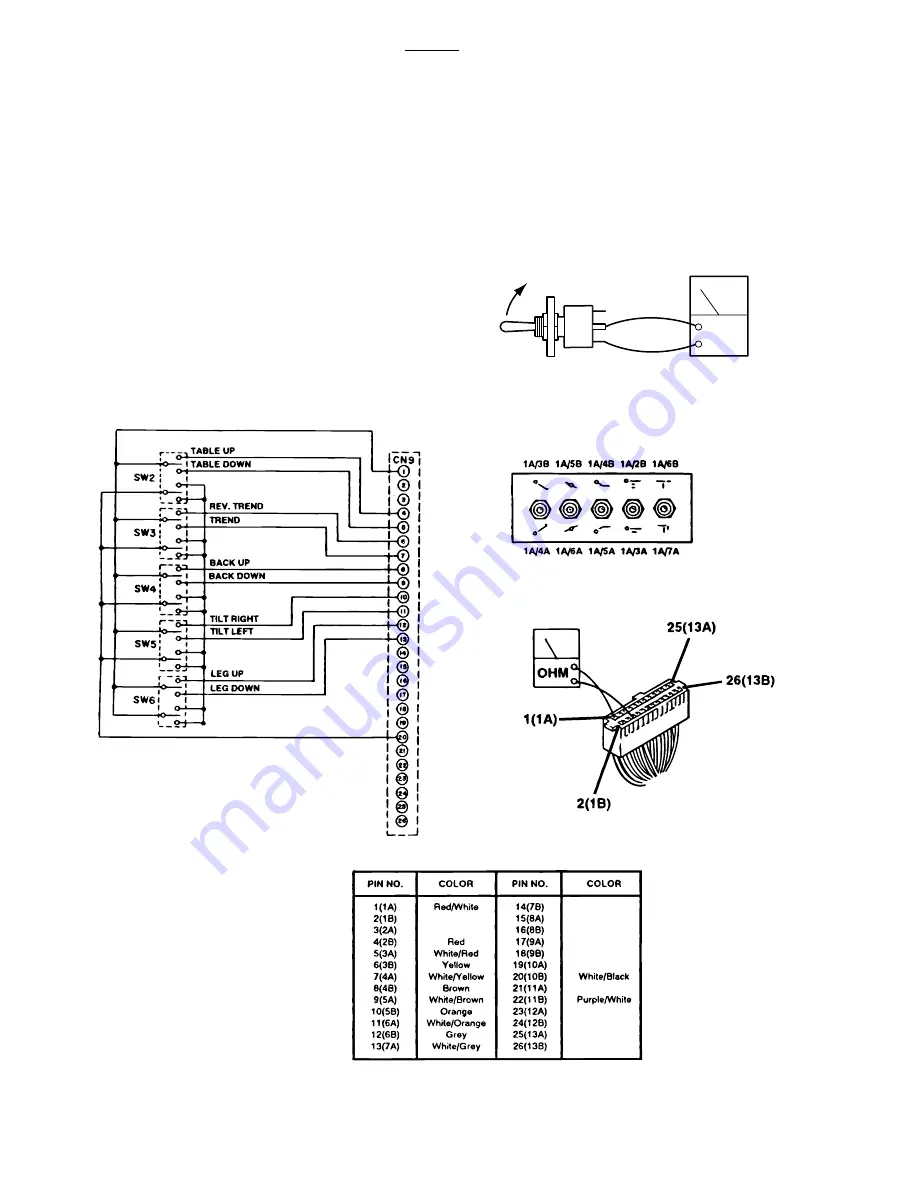
6-8. Auxiliary Switches
The following tests will determine if the auxiliary
switches are functioning properly.
a. Switch Test
Disconnect connector CN9 at the Relay Box and
using an ohmmeter check for continuity at the
connector pins (pin 1A common) while activating
the appropriate switch. See figure 6-16. Meter
should read 0 ohms.
b. Test Results
If proper meter readings are not received, test the
individual switches as necessary. Using an ohm-
meter, test the operation of an individual switch
with the (+) test lead at the center terminal of the
switch and the (-) test lead at the terminal opposite
the direction of the switch actuation. See figure 6-
17. Meter should read 0 ohms. If the switches
check out, the problem would have to be in the
wires or connector CN9.
Figure 6-17. Auxiliary Switch Test
Figure 6-16. Auxiliary Switch Connector CN9
6002B
Summary of Contents for ELITE 6002
Page 2: ...Page 52...
Page 8: ...Page 52...
Page 29: ...Page 21 Figure 4 1 6002 Electrical Circuit Block Diagram...
Page 59: ...Page 51 VR2 VR3 VR1 Figure 7 2 Relay Box Adjustments Model 6002B...
Page 60: ...Original printing 5 03 Revised 8 05...
Page 61: ...Page 52...
Page 62: ...Page 58 500036thStreetS E GrandRapids MI 49512 1 800 SKYTRONor1 616 957 0500 FAX1 616 957 5053...


