background image

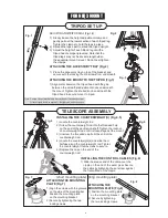
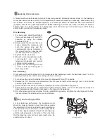
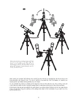
Note: Loosen the azimuthal adjustment knobs if mount does not 

          fit into tripod head completely. Retighten knobs to secure. 

8

FOR EQ5 MOUNT

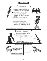
ATTACHING MOUNT TO TRIPOD (Fig.20)

1) Align metal dowel on the tripod head with the gap 

    between the azimuthal adjustment knobs underneath 

    the mount. Tighten the knurled knob underneath the 

    tripod head to secure mount to tripod.

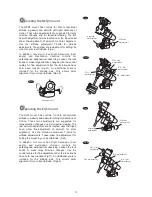
ADJUSTING THE TRIPOD LEGS (Fig.18)

1)  Slowly loosen the height adjustment clamp  and

     gently pull out the lower section of each tripod leg. 

     Tighten the clamps to hold the legs in place. 

2)  Spread the legs apart to stand the tripod upright. 

3)  Adjust the height of each tripod leg until the 

     tripod head is properly leveled. Note that the 

     tripod legs may not be at same length when 

     the equatorial mount is level. Do not over tighten

     the clamps.

ATTACHING THE ACCESSORY TRAY (Fig.19)

1)  Place th e accessory tray on top of the bracket, and  

      secure with the locking thumb screws from underneath.

Fig.19

Fig.20

Fig.21

Fig.22

Fig.23

Fig.24

Fig.18

Note: The screws should align with the 

          grooves in the side of the mounting bar.

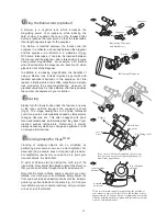
INSTALLING COUNTERWEIGHT (Fig.21, 22)

1) Locate counterweight rod. 

2) Screw counterweight rod into threaded hole on the 

    end of the declination shaft. Tighten locknut on the 

    counterweight rod until it is locked against the mount. 

3) Unscrew the threaded cap from the end of the 

    counterweight rod.

4) Locate the counterweights and slide them halfway 

    along the counterweight rod. Tighten the counterweight 

    thumb screws to secure.

5) Replace the cap on the end of the counterweight rod. 

ATTACHING THE MOUNTING 

PLATE (Fig.23)

1) Position  the mounting plate 

    on the mounting bracket.

2) Secure by tightening the two 

    locking screws.

ATTACHING THE 

MOUNTING PLATE (Fig.24)

1) Position the mounting plate 

    on the mounting bracket.

2) Secure by tightening 

    the two locking screws.

(short mounting plate)

(long mounting plate)

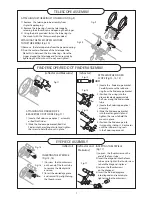
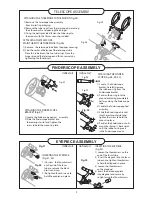
TRIPOD SET UP

TELESCOPE ASSEMBLY

Summary of Contents for EQ5

Page 1: ...INSTRUCTION MANUAL Telescopes with NEQ3 EQ5 Mount 031007V3 ...

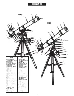
Page 2: ... shown Altitude Adjustment T bolts Counterweight Rod Counterweight Counterweight Thumb Screw Azimuth Adjustment Knob Dec Lock Knob Tube Rings A B C D E F G H I J K L Dust Cap Mask Remove before Viewing Sun Shade Objective Lens Telescope Main Body Piggyback Bracket Finderscope Finderscope Bracket Alignment Screw Eyepiece Diagonal Focus Tube Focus Knob 1 2 3 4 5 6 7 8 9 10 11 12 Polarscope Holder no...

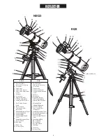
Page 3: ...ustmentT bolts Azimuth Adjustment Knob Counterweight Counterweight Thumb Screw Counterweight Rod R A Lock Knob Dec Lock Knob Dec Control Knob Tube Rings a Tripod Leg Accessory Tray A B C D E F G H I J Dust Cap Mask Remove before Viewing Focus Tube Finderscope Finderscope Bracket Finderscope Adjustment Screws Eyepiece Focus Knob Piggyback Bracket Telescope Main Body Primary Mirror Position 1 2 3 4 ...

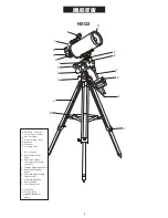
Page 4: ... Eyepiece Diagonal Focusing Knob 1 2 3 4 5 6 7 8 9 R A Lock Knob Dec Flexible Control Cable Polarscope Holder Polarscope not shown optional Altitude Adjustment T bolt Azimuth Adjustment Knobs Counterweight Locking Thumb Screw Counterweight Rod Dec Lock Knob Dec Setting Circle a b Tripod Leg Accessory Tray Height Adjustment Clamp NEQ3 ...

Page 5: ... to Observe Chooling the Telescope AdaptingYour Eyes Collimating a Newtonian reflector Collimating a refractor with the adjustable objective lens cell CleaningYour Telescope 6 10 6 6 7 7 10 10 11 11 12 12 13 13 13 14 16 18 19 19 19 19 19 20 22 22 8 8 9 9 19 20 Appendix A Precise polar alignment for Northern Hemisphere I Appendix B Optional Accessories III Appendix C Recommended Reading IV TABLE OF...

Page 6: ...bscrews to secure 5 Replace the cap on the end of the counterweight rod INSTALLING THE CONTROL CABLES Fig 6 1 Slide the sleeve end of the cable over the nipple on the end of the worm gear Secure the cable by tightening the set screw against the flat surface of the nipple TRIPOD SET UP TELESCOPE ASSEMBLY Fig 7 Fig 8 ATTACHING THE MOUNTING PLATE Fig 7 1 Align the screws with the grooves on the side ...

Page 7: ... assembly 4 Slide the finderscope bracket into the rectangular slot and tighten the screw to hold the mount in place 5 Position the finderscope into its mount by sliding it backwards until the rubber o ring seats in the finderscope mount reflector and Maksutov refractor reflector refractor and Maksutov ATTACHINGTHE FINDERSCOPE BRACKET RED DOT FINDER Fig 11 1 Locate the finderscope optical assembly...

Page 8: ...accessory tray on top of the bracket and secure with the locking thumb screws from underneath Fig 19 Fig 20 Fig 21 Fig 22 Fig 23 Fig 24 Fig 18 Note The screws should align with the grooves in the side of the mounting bar INSTALLING COUNTERWEIGHT Fig 21 22 1 Locate counterweight rod 2 Screw counterweight rod into threaded hole on the end of the declination shaft Tighten locknut on the counterweight...

Page 9: ...finderscope tube 3 Locate the finderscope optical assembly 4 Slide the finderscope bracket into the rectangular slot and tighten the screw to hold the mount in place 5 Position the finderscope into its mount by sliding it backwards until the rubber o ring seats in the finderscope mount reflector refractor reflector refractor ATTACHINGTHE FINDERSCOPE BRACKET Fig 27 1 Locate the finderscope optical ...

Page 10: ...ky The Red Dot Finder is equipped with a variable brightness control azimuth adjustment control and altitude adjustment control Fig b The Red Dot Finder is powered by a 3 volt lithium battery located underneath at the front To use the Finder simply look through the sight tube and move your telescope until the red dot merges with the object Make sure to keep both eyes open when sighting Azimuth adj...

Page 11: ... telescope mount and allows precise control of micro adjustment A balanced telescope is specially critical when using the optional clock drive for astrophotography The telescope should be balanced after all accessories eyepiece camera etc have been attached Before balancing your telescope make sure that your tripod is balanced and on a stable surface For photography point the telescope in the dire...

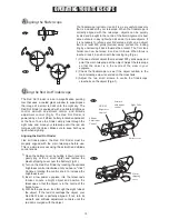
Page 12: ...ude axis This allows polar alignment for your local latitude Fig e2 Fig f Altitude adjustment Azimuth adjustment Fig e Fig e1 Fig f1 Fig e2 Operating the NEQ3 mount The NEQ3 mount has controls for both conventional altitude up down and azimuth left right directions of motion These two adjustments are suggested for large direction changes and for terrestrial viewing The two azimuth adjustment knobs...

Page 13: ...le reducing the field of view It expands the cone of the focussed light before it reaches the focal point so that the telescope s focal length appears longer to the eyepiece The Barlow is inserted between the focuser and the eyepiece in a reflector and usually between the diagonal and the eyepiece in a refractor or a maksutov Fig g With some telescopes it can also be inserted between the focuser a...

Page 14: ......

Page 15: ...rallel to the ground If so it is time to perform a meridian flip This is necessary to prevent your telescope from eventually colliding with the mount or tripod To do a meridian flip rotate your telescope 180 degrees in Dec and lock the Dec axis Now rotate your mount 12H in RA and lock the RA axis Using the setting circles to assist you will help you do this more accurately When finished you should...

Page 16: ...nt the fewer Dec adjustments you will need to make Using the Setting Circles 0 2 4 6 10 8 1 1 0 23 23 22 22 21 21 4 2 2 20 20 3 3 4 9 8 10 11 12 Altair Vega Deneb SE E NE First you need to calibrate the RA axis Fig n To do this align your telescope to an object with known coordinates and then rotate the RA setting circle to show those coordinates Leave the setscrew unlocked at this point Your Dec ...

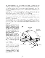
Page 17: ...ck the RA setscrew by tightening it fully When you are ready to move on to the next object unlock the RA set screw then rotate the RA and Dec axes until you arrive at the desired coordinates Plane of local horizon Nadir Equatorial Mount Northern Hemisphere Mount aligned on North Celestial Pole Zenith Right Ascension Apparent movement of stars Plane of Celestial Equator Meridian Line Declination Ob...

Page 18: ...lescope in mm by the magnification Exit Pupil Diameter of Primary mirror in mm Magnification For example a 200mm f 5 telescope with a 40mm eyepiece produces a magnification of 25x and an exit pupil of 8mm This combination can probably be used by a young person but would not be of much value to a senior The same telescope used with a 32mm eyepiece gives a magnification of about 31x and an exit pupi...

Page 19: ...tivity The best conditions will have still air and obviously a clear view of the sky It is not necessary that the sky be cloud free Often broken cloud conditions provide excellent seeing Do not view immediately after sunset After the sun goes down the Earth is still cooling causing air turbulence As the night goes on not only will seeing improve but air pollution and ground lights will often dimin...

Page 20: ...all Fig q 1 The secondary mirror is aligned by adjusting the three smaller screws surrounding the central bolt The primary mirror is adjusted by the three adjusting screws at the back of your scope The three locking screws beside them serve to hold the mirror in place after collimation Fig q 2 Aligning the Secondary Mirror Point the telescope at a lit wall and insert the collimating cap into the f...

Page 21: ...pping at the point where the reflected image of the secondary mirror is closest to the primary mirrors edge Fig q 5 When you get to that point stop and keep your hand there while looking at the back end of your telescope is there an adjusting screw there If there is you will want to loosen it turn the screw to the left to bring the mirror away from that point If there isn t an adjusting screw ther...

Page 22: ...igher power eyepiece while keeping the image centered The in focus star image will have a bright innermost point a slightly fainter inner ring and a fainter still outer ring that is hard to see Fig r 1 If it doesn t look like this or you can t reach focus then start with take out your star diagonal and look at the image slightly out of focus this will allow you to gauge the deflection A typical of...

Page 23: ...G THE MOUNT Locate a distant object and place it under the cross at the centre of the polarscope reticule Rotate the mount in RA 180 degrees i e 12 hours on the RA setting circle Note the displacement of your target from the centre of the crosshairs Fig s 1 If it is not displaced at all it means your polar scope reticule is already properly aligned and you don t need to do any more If it is displa...

Page 24: ...e with Polaris and the North Celestial Pole NCP the point in space at which you want to aim your polar axis to achieve an accurate polar alignment Kochab rotates around the NCP the way the hour hand rotates around a clock face but it takes Kochab nearly 24 hours to make one revolution We can use this behavior to help us achieve an accurate polar alignment quickly and simply First identify the brig...

Page 25: ...ill allow several nights of observing 2x and 8x tracking speeds 2x and 4x for EQ1 model are available through the hand control ler Motor hand controller and battery case are included COLLIMATING EYEPIECE The Sky Watcher Collimation Eyepiece is ideal for precise collimation of Newtonians and refractors with an adjustable lenscells This special eyepiece fits into 1 focusers or diagonals Alignment is...

Page 26: ... Them by Guy J Consolmagno and Dan M Davis Cambridge University Press New York 3rd edition 2000 IV Amateur Astronomy The Great Atlas of the Stars by Serge Brunier Constellation photography by Akira Fujii Firefly Books Willowdale ON Canada 2001 A Manual Of Advanced Celestial Photography by Brad D Wallis and Robert W Provin Cambridge University Press New York 1984 Astrophotography An Introduction by...

Page 27: ......

Page 28: ...o the receptacle labeled Dec out on the mount Fig 6 The hand control cable has a RJ 45 connector on both ends Plug one end into the hand control and the other into the outlet on the mount Locate the power cord Make sure that the power switch on the motor controller is OFF Plug the cigarette lighter end of the cable into the battery and the other into the motor controller 5 6 7 8 Fig 1 Fig 2 191206...

Page 29: ...INSTRUCTION MANUAL SynScan TM 140303V4 Copyright Sky Watcher ...

Page 30: ...er Speed 25 PART VII CONFIGURE THE HAND CONTRL 7 1 Display Keypad 26 7 2 Alignment Star Filter 26 7 3 Sorting Method of the Alignment Star List 26 7 4 Naming of Stars 26 Basic Operations Intermediate Operations PART VIII AUXILIARY FUNCTIONS PART IX CONNECTING TO A COMPUTER PART X UPDATING FIRMWARE PART XI ADVANCED FUNCTIONS PART XII USING A SYNSCAN GPS MODULE APPENDIX I ELIMINATING CONE ERROR 41 A...

Page 31: ...e movements of the Declination Dec axis for an equatorial mount or altitude axis for an Alt azimuth mount In most cases pressing the RATE 2 key will invoke the operation of choosing a slewing speed The LCD screen will display Set Speed followed by the current speed as Rate x Press a number between 0 and 9 to select a new speed Press the ENTER key to return to the previous display If the user does ...

Page 32: ...le in Southern Hemisphere Counterweight rod is at its lowest position The telescope points towards the Northern Celestial Pole in Northern Hemisphere or the Southern Celestial Pole in Southern Hemisphere To operate the SynScan hand control in Full Feature mode no particular home position is required To operate the SynScan hand control in Easy Tracking mode the mount should be setup as close to hom...

Page 33: ...d mm dd yyyy format i e 10 24 2012 for Oct 24 2012 press the ENTER key to confirm and pro ceed to the next step Press the ESC key to return to the Geographic Coordinates step When Enter Time is displayed enter the current local time in 24 hour format i e 18 30 00 for 6 30pm Press the ENTER key to display the entered time in 12 hour for mat Press the ENTER key again to confirm and proceed to the ne...

Page 34: ... by the hand control to prevent the objects drift in the FOV of the telescope PART III ALIGNMENT 3 Now users can use the direction keys to move the telescope to align with the 1st alignment star That is center the 1st alignment star in the FOV of the finder scope and then center it in the FOV of the telescope s eyepiece press ENTER key to confirm centering of the star and proceed to the next step ...

Page 35: ...ning the 2nd Star Cancellation During Aligning Process 1 If the 1st alignment star is not a planet the LCD screen will display Choose 2nd Star other wise it will display Choose 1st Star 2 Use the scrolling keys to browse through a list of star names and press ENTER key to pick the one on the screen as the 2nd alignment star The mount will then automatically slew and point the telescope towards the...

Page 36: ...gnment users may press the ESC key to stop the mount The hand control screen will display MOUNT STOPPED Press any key 2 Press any key and the SynScan hand control will ask the user to select another alignment star 3 Press the ESC key again the LCD screen will display Exit Alignment 1 YES 2 NO Press key 1 to exit the alignment process press key 2 to go back to choose an alignment star PART III ALIG...

Page 37: ...then it is not necessary to choose the 3 star alignment to align the mount Use 1 star alignment or 2 star alignment instead The Brightest Star Alignment is designed for entry level users who cannot identify stars in the night sky and the 2 Star alignment is for users who know the names of the stars in the night sky Both alignment methods provide the same level of precision Rules for choosing align...

Page 38: ...the 3 digits Messier index number which is between 1 and 110 Use the number keys on the keypad to enter a number at the cursor position Use the left or right direction keys to move the cursor A 3 digit number starting with a 0 is acceptable Ex 001 01 1 Press ENTER key to proceed to the next step The screen will display View Object Press the ESC key to return to the previous step Press the ENTER ke...

Page 39: ...s refer to Section 5 1 for de tails PART V LOCATING OBJECTS 5 5 Locating SAO Stars 1 Choosing an Object 2 View Information on the Object 3 Locate the Object Press the OBJECT shortcut key The screen will display OBJECT LIST in the top row Use the two scrolling keys to browse the list until SAO Catalog is displayed and then press the ENTER key The screen will then display SAO Catalog SAO 0000xx to w...

Page 40: ...d object PART V LOCATING OBJECTS Recalling Objects 1 Press the USER shortcut key The screen will display USER OBJECT Recall Object Press the ENTER key 2 Use the scroll keys to browse through a pre defined objects list which is indexed from 1 to 25 and then press ENTER If the selected object has not been defined before the SynScan hand control will stay at this step for the choosing of another obje...

Page 41: ...s When a user asks the SynScan hand control to locate an object whose elevation exceeds the limits the SynScan hand control will display Target is over slew limits and will not start the mount slewing PART VI CONFIGURE THE TELESCOPE MOUNT 6 4 Enable Disable Auxiliary Encoder 6 5 Setting Autoguider Speed The screen will display Set Elev Limits in the top row and Upper XXX Xo at the bottom row Use t...

Page 42: ... and Local Sidereal Time 8 5 Display Version Information 1 Press the MENU shortcut key 2 Use the scroll keys to select Date and press the ENTER key to edit the date Press the ENTER key to apply change or press the ESC key to exit Note The setting of the date is in mm dd yyyy format i e 10 24 2012 3 Use the scroll keys to select Time and press the ENTER key to edit the time Press the ENTER key to a...

Page 43: ...lue is the polar alignment offset in azimuth These data is valid only after a 2 star alignment or a 3 star alignment PART VIII AUXILIARY FUNCTIONS 8 11 Synchronizing Encoders If the mount lost the correct position of any of its two axes for example the axis is manually moved the pointing accuracy will be poor when the SynScan hand control tries to locate an object Providing the base of the mount i...

Page 44: ...mainly used to update the motor controller s firmware Access the menu UTILITY FUNCTION PC Direct Mode and press the ENTER key The screen will display PC Direct Mode Press ESC to exit Press and hold the ESC key more than 1 second to exit PC Direct Mode Users can still use the direction keys to move the telescope mount PART X UPDATING FIRMWARE 10 1 Hardware Requirements 10 2 Preparation 10 3 Updatin...

Page 45: ... can park the telescope to keep the alignment data PAE data and PEC data and start observing in the next session without redoing the alignment and calibration Parking 1 Access the menu UTILITY FUNCTION Park Scope and press the ENTER key 2 The screen will display Park to Use the scroll keys to choose one from the following parking position and press the ENTER key Home Position Park the telescope to...

Page 46: ...the end of the alignment the Syn Scan hand control will display the polar alignment error refer to Section 3 3 Users can use the data to determine whether it is necessary to adjust the polar alignment 2 Press the MENU shortcut key and then access to sub menu Alignment Polar Alignment press the ENTER key to proceed to the next step 3 The screen will display Select a Star Use the scroll keys to brow...

Page 47: ...e same port on the camera 2 Using the multi purpose port on the SynScan hand control The SynScan hand control uses 2 pins The SHUTTER and COMMON pins in the dia gram of Appendix 3 of its multi purpose port to control the shutter release of a DSLR camera Users may use a proper shutter release cable to connect the SynScan hand control and a camera 1 Press the UTILITY shortcut key access to sub menu ...

Page 48: ...atorial mount only All equatorial mount has periodic tracking error which is not critical for visual observing but might lower the picture quality of long exposure astrophotography The SynScan hand con trol has the periodic error correction PEC function to improve the tracking performance for astrophotography Depending on the model of the equatorial mount there are two types of PEC One is soft war...

Page 49: ...ror If the pointing accuracy becomes poor and most of the error is on the R A axis that is the object can be brought back to the center of the eyepiece using the left or right di rection keys it means that the cone error of the telescope mount system is quite large If the telescope s optical axis is not perpendicular to the declination axis of the equatorial mount then there is cone error in the t...

Page 50: ...f everything is fine the testing will go to Step 9 Otherwise the SynScan hand control will show EEPROM ERROR or Flash ERROR Press ENTER to continue in such case 9 Check keypad and other features The screen will display Key in the top row If a key is pressed the name of the key will be displayed The power voltage will be displayed on the bottom row of the screen Supported Mount EQ Mount and Alt Az ...

Page 51: ...SynScan TM ...
Reviews: