background image

……………………………………………………

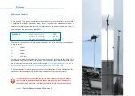
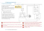
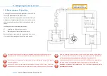
10. Wiring / Eletrical Connection


Seite 29 

| Owners Manual SkyWind NG, Version 5.1


…………………………

10.3 Setting up the inverter


To start the process push the 

House

“ 

button on the right side of the display. Use the 

up

“ 

and 

down

“ 

arrow  buttons  to  navigate  to  the 

Gear  Wheel

“ 

symbol  on  the  display.  Select  it  by 

pushing the 

Gear Wheel

“ 

button on the right side of the display.  


Navigate  to  the 

Current  Curve  Adjust

“ 

tick

-

box  using  the  arrow  buttons  and  activate  it  by 

pushing the 

Gear Wheel

“ 

button on the right side of the display.  Now decide for either 

Power 

Curve A

 or 

Power Curve B:


Power Curve A 

Will only work on sites with a constant and laminar wind flow is (see manual). 


Power Curve B 

Should be chosen for any site a laminar flow of wind cannot be guaranteed . 


Once you have determined which power curve fits your site you navigate to the first data field 
(23V)  using  the  arrow  buttons  and  activate  it  with  the 

Gear  Wheel

“ 

button.  Use  the  arrow 

buttons to select the right value from the power curve. Then confirm the value by again pushin 
the 

Gear Wheel

“ 

button. Proceed by entering the entire power curve. 


After  finishing  with  the  52V  value,  navigate  to  the 

Dumpload

“ 

tick

-

box  and  activate  it  by 

pushing the 

Gear Wheel

“ 

button. Next select the voltage value and set it to 

40  V

. Once again 

confirm your selection by pushing the 

Gear Wheel

“ 

button. 


Finally  push  the 

Home

“ 

button  on  the  right  of  the  display.  A  menu  will  pop

-

up  asking  you 

wether  you  would  like  to  save  your  entries.  Navigate  to  the 

Yes

“ 

option  and  confirm  it  by 

pushing the 

Gear Wheel

“ 

button. 


INSECURE? 

CHOSSE POWER CURVE 

B

 AND, WENN IF EVERYTHING WORKS WELL, TRY TO CHAN-

GE  TO  POWER  CURVE 

A

  AFTER  THE  FIRST  YEAR.  IF  THE  POWER  PRODUCTION  GETS  WORSE 

CHANGE BACK TO B. 


…………………………

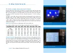
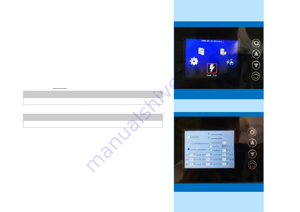
The inverter main menu


23V


26V


30V


34V


38V


42V


46V


50V


52V


A


018


025


033


047


058


074


093


117


142


x0.1A


23V


26V


30V


34V


38V


42V


46V


50V


52V


B


018


024


034


055


072


094


115


134


155


x0.1A


…………………………

…………………………

The power curve adjustment menu


Summary of Contents for NG

Page 1: ...witch to page 55 for english language Bitte beachten Sie immer die aktuelleste Version dieser Bedienungsanleitung welche Sie in der Infothek auf www myskywind com oder herunterla den können http www myskywind com SkyWind Infothek Flyer Broschuren Vide infothek flyer broschuren videos html ...

Page 2: ...ise zur Anbringung der Rotorblätter 19 8 Aufstellungsort des SkyWind NG 20 8 1 Aufstellungsort 20 Ziff Inhalt Seite 8 2 Verwirbelung 21 8 3 Ertragsprognose und Ertrag 22 9 Mast 23 9 1 SkyWind NG Masten 23 9 2 Hinweise zur Dämpfung von Masten 24 9 3 Betrieb auf dem Hausdach oder an Gebäuden 25 9 4 Standsicherheit 26 10 Verkabelung Anschluss 27 10 1 Verkabelung 27 10 2 Wechselrichter 28 10 3 Wechsel...

Page 3: ...ten Sie daher auf Veränderungen gegenüber Ihrer ersten Version Eventuell ergeben sich sicherheitsrelevante Anpassungen Windgeneratoren müssen wie andere Quellen elektrischer Energie gemäß der durch den Staat und örtliche Bestimmungen begründeten Richtlinien installiert werden Bitte informieren Sie sich diesbezüglich Gegebenenfalls sind behördliche Genehmigungen Zulassungen Prüfungen Zertifikate od...

Page 4: ...st durchzuführen Bitte beachten Sie die getroffene Beschaffenheitsvereinbarung Für den Installateur sind sämtliche Vorgaben dieser Bedienungsanleitung verbindlich Er über nimmt die Haftung für korrekte Umsetzung und Funktion des Aufbaus Er wird bei der Installati on der Anlagen neben der Bedienungsanleitung immer die Installationshinweise in Ihrer je weils aktuellen Form berücksichtigen die dieser...

Page 5: ...tomatische Sturmabschaltung für SkyWind NG Steuerungseinheit Zeitrelais Hochstromrelais 6 Hinweisblatt zum Download dieser Bedienungsanleitung Ein etwaiges Mastsystem stellt niemals einen Bestandteil dieser Windkraftanlage dar SkyWind Energy stellt KEIN Mastsystem selbst her sondern vertreibt gegebenenfalls Lösungen anderer Hersteller für diesen Windkraftanlagentyp Eine Haftung für kor rekte Funkt...

Page 6: ...sind Nicht bestimmungsgemäße Verwendung Nichtbeachten der Montage und Betriebsanleitung Fehlender Dokumentation von Einstellungen und Montage Betrieb mit nicht funktionsfähigen Sicherheits oder Schutzeinrichtungen Weiterbenutzung trotz Auftreten eines Mangels Unsachgemäßes Montieren Inbetriebnehmen Bedienen und Warten Eigenmächtige Veränderungen am Gerät Einbau von Zusatzkomponenten die nicht für ...

Page 7: ...torblattes von der Gene ratorgondel weg zeigen Verwenden Sie niemals andere als die Originalteile Niemals beschädigte Teile verwenden Keine Mängel in den Versorgungsleitungen Höhere Gewalt fällt nicht in die Gewährleistung oder Garantie Sturmabschaltung Schalleinstellung Die Spannungsmessung das Zeitrelais und das Starkstromrelais müssen korrekt montiert und eingestellt werden Die Montage des Roto...

Page 8: ... nicht unterschätzt werden Achtung Der Schwer punkt der Gondel liegt nicht am Mastadapter 5 2 Elektrische Gefahren Bitte beachten Sie dass die persönlichen Gefahren durch elektrischen Strom immer existieren Handeln Sie niemals leichtfertig Lassen Sie beim Anschließen dieses oder anderer Geräte stets Vorsicht walten Hitze in elektri schen Leitsystemen ist oft ein Resultat aus zu viel Strom in zu dü...

Page 9: ...jeglicher Installati onsprozesse kurz Die Turbine wird dadurch abgeschaltet Bitte beachten Sie dass es sich um ein mechanisches Gerät mit teilweise großen Belastungs spitzen handelt Es ist daher von äußerster Bedeutung dass die in dieser Bedienungsanlei tung und den ergänzenden Dokumenten aufgeführten Schritte äußerst gründlich und sorg sam durchgeführt werden Andernfalls kann es zu Schäden und Mi...

Page 10: ...it Installieren Sie die Masten und ggf Entkoppler Montieren Sie den Wechselrichter und programmieren Sie diesen Sh S 27 38 Montieren Sie die Sturmabschaltung und setzen Sie das System AUS Sh S 35 38 Bereiten Sie die Gondel auf die Installation vor und montieren Sie das Kabel Sh S 17 Führen Sie die Kabel durch den Mast und befestigen Sie die Turbine Beschichten Sie die Gondel nun ausgiebig mit Schu...

Page 11: ...den sein Dokumentieren Sie unbedingt Ihre Installation detailliert und mit Fotos Nur wenn Sie im Falle eines Problems den exakten Zustand der Anlage wiedergeben und belegen können besteht ein Anspruch auf Gewährleistung Stimmt die Kennlinie War die Bremse richtig eingestellt War der Leitungstest durchgängig Zu Ihrer eigenen Absicherung empfehlen wir Dokumentieren Sie alle Einstellungen Aufbauten u...

Page 12: ...V DC Maximaler Laststrom 30 A Kurzschlussstrom 2 s 45 A Restinduktivität 4 8 mH Netzeinspeisung Optional Mitgelieferter 1kW Windwechselrichter Batterieladung Optional Mitgelieferter 30 A 12 24 V Laderegler Bremssystem Wirbelstrom Stall Maximale Schubkraft Betrieb 250 N Schutzgrad IP 56 Nenngeschwindigkeit Ca 50 km h 14 m s Auslegungsgeschwindigkeit Ca 29 km h 8 m s Abschaltgeschwindigkeit Späteste...

Page 13: ... 22 65 V Bremslastregelung DC seitig integriert MPPT Optimierung Ja Überstromschutz DC Ja Überspannungsschutz DC Ja Verpolungsschutz DC Ja Überhitzungsschutz Ja Inselnetzschutz Ja Schutzgrad IP 20 Konformität VDE AR N 4105 2011 08 ggf NA Schutz erforderlich VDE 0126 1 1 2013 Lagertemperaturbereich 40 65 C Betriebstemperaturbereich 20 50 C Luftfeuchtigkeit Nicht kondensierend Displayfunktion Leistu...

Page 14: ...lungsschutz Akku Ja Verpolungsschutz Wind Ja Übertemperaturschutz Ja Temperaturfühler Ja Step Up Funktion Ja Impulsladung Ja Betriebsbereich 25 C bis 60 C Gemeinsame Masse Ja Schaltbarer Lastausgang Ja Gehäuse Metall IP Schutzgrad 20 Ladeschlussspannung 14 1 V 28 2 V Erhaltungsladung 13 7 V 27 4 V Luftfeuchtigkeit Nicht kondensierend Abschaltspannung 10 5 V 21 0 V Rücksetzspannung 12 5 V 25 0 V Ba...

Page 15: ...läche Maschinenhaus Gesamt Zylinder 0 214m Ihre Werbung Ihr Logo 0 16m 0 35m 0 088m 0 032m Sicherheitshinweise Gerät für Menschen unzugänglich montieren Installation durch qualifiziertes Personal durch führen lassen Die Montage muss den angegebenen Kräften gewachsen sein Montage aus schließlich nach Bedienungsanleitung Achten Sie auf ausreichende Festigkeit des Masten Der moderne Blickfang für ene...

Page 16: ...ische Sturmabschaltung ein und stellen Sie diese korrekt ein Setzen Sie dann den Hauptschalter auf AUS Dokumentation 10 Ziehen Sie die Arretierungsschrauben des Mastadapters gleichmäßig fest und achten Sie auf eine exakt lotrechte Ausrichtung der Gondel 11 Prüfen Sie das die Gondel und sonstige Komponenten spielfrei und fest an Ihren Positionen befestigt sind Prüfen Sie dass die Windnachrichtungsl...

Page 17: ...hrumpfschlauchisolation Durch festes Anziehen des Kabelbinders wird sichergestellt dass später keine Dreh oder Zug kräfte auf die Kabelverbindungen kommen Da der SkyWind aus funktionalen Gründen keinen Schleifring besitzt ist die korrekte Durchführung dieser Schritte äußerst wichtig Ein Schleifring würde die Lebensdauer der Turbine jedoch drastisch reduzieren Achten Sie darauf den Übergang in den ...

Page 18: ...Sie auf korrekte Ausrichtung und absolut festen Sitz da der Gehäusedeckel für die Kraftschlüssigkeit der Gondel maßgeb lich ist Fixieren Sie die Gehäuseschrauben mit einem Drehmoment von 2 Nm Die Windnachrichtungsblockierungsschraube rot kann die Drehung der Gondel blockie ren um Ihnen die Installation zu erleichtern Nach Abschluss der Montage darf Sie die Gondel nicht in der Drehung einschränken ...

Page 19: ...nde Horizontalachswindkraftanlage Der Wind trifft also von hinten über Gondel und Mast auf das Rotorblatt Die Anlage richtet sich dann von alleine in die aktuelle Windrichtung aus Für eine korrekte Montage zeigen die abgeknickten Enden des Rotors von der Gondel weg Blickt man von vorne auf die Anlage also Rotor vor Mast wird sich die Anlage im Uhrzeigersinn drehen Um sicherzugehen dass sich der Ro...

Page 20: ... verursachte Luftwirbel mindern die Effizienz jedes Windkraftwerks Daher stellen Sie die Turbine an einem Ort auf an dem der möglichst unbeschränkteste am meisten laminare freiwehendste Wind herrscht Windenergie ist die kubische Funktion der Windgeschwindigkeit Dies bedeutet dass geringe Veränderungen der Windgeschwindigkeit drastische Auswirkungen auf die Leistung haben Da her sollte Ihre Windanl...

Page 21: ...halten Dies minimiert die Verluste durch Randwirbel Bei Missachtung kann sich die Turbine nicht mehr kor rekt in den Wind richten und macht einen eiernden Eindruck oder läuft sogar falschherum Rotorschaden droht Verwenden Sie für die Montage von Turbinen auf einem normalen Spitzdach folgende Faustregel für die Wahl des Aufstellungsortes A Wählen Sie die Mitte des Daches für eine einzelne Turbine B...

Page 22: ...er dürfte der 5 m s Beispielstandort in dieser Rechnung tatsächlich etwa 750 kWh pro Jahr erwarten Dieser Ertrag wird an vielen Standorten großteils in Herbst und Winter erzeugt werden Kann ein Monatsertrag im Sommer teils nur eine kWh betragen kann dieser Ertrag im Winter schon in wenigen Stunden erzeugt werden Das ist normal Für eine Abschätzung des Jahresertrag benötigen Sie daher eine computer...

Page 23: ...ttes 70 mm Mastdurchmesser nicht über schritten werden sh Bild Andernfalls treffen Wirbel des Masten auf das Rotorblatt und führen zu helikopterartigen Geräuschen sowie Vibration die Ihre Anlage beschädigt Falsch Entscheidend für geringe Vibrationsübertragung ist eine ausreichende Wandstärke bzw ein ausreichender Mast durchmesser die ein federn im Mast ausschließen Ein federnder oder in sich schwi...

Page 24: ...a 10 50Hz bedingt durch Ihren Betrieb anregt Wenn die Montage und der Mast in diesem Be reich zu Eigenschwingungen angeregt werden können führt dieses binnen kurzer Zeit zu einer Zerstörung der Anlage sowie einem extrem lauten Betrieb Grundsätzlich sollte die Anlage immer möglichst weit von Trittstufen im Dach festen Verbin dungen durch die Dachisolierung sowie darunter liegenden Schlafzimmern ent...

Page 25: ...etet seinen Kunden aus Gründen der Nutzungsfreundlichkeit die gesammelte Lieferung von Windkraftanlage und Zubehörteilen anderer Hersteller an SkyWind Energy ist jedoch nicht Hersteller dieses Zubehörs und kann insbesondere keine Haftung für deren Funkti on oder für Änderungen in der laufenden Produktion übernehmen Jedwede Ausführung zu Masten und Entkopplungen stellt lediglich Empfehlungen aufgru...

Page 26: ...Abschaltung bei zu hohen Windgeschwindigkeiten Grundsätzlich sollten Sie 60 mm Masten nur für kurze Mastlän gen bis 2 m und mit einer Dämpfung einsetzen Der Mast darf keine Schwingung in sich aufbau en können Längere Masten sollten daher immer ausreichende Durchmesser Wandstärken und Materialien aufweisen Jede Statik muss immer eine mindestens 3x Sicherheit aufweisen Achten Sie darauf dass bei sta...

Page 27: ...ches ein Ein automati sches Sturmabschaltungssystem wird in der Regel immer mitgeliefert sein Ein Betrieb ohne Abschaltsystem ist unzulässig und lebensgefährlich Hinweis Alle elektrischen Kabel müssen physisch geschützt sein Verwenden Sie DC seitig nur Solarflexkabel diese sind doppelt isoliert Bei Wand oder Erdverlegung beachten Sie die Richtlinien Hinweis Die Gierung kann maximal mit 20kg Kabelg...

Page 28: ...n Kabel mit den beiden schwarzen DUMPLOAD Kontakten an Ihrem Wechselrichter Multifunktionsdisplay Ihr Wechselrichter besitzt ein LCD Farbdisplay mit Hintergrundbeleuchtung Über dieses kön nen Sie am Regler jederzeit aktuelle Werte ablesen oder Einstellungen vornehmen Für die opti male Funktion an Ihrem Standort muss der Wechselrichter Ihres SkyWind NG auf die Gegeben heiten vor Ort eingestellt wer...

Page 29: ...en wechseln Sie mit der Pfeiltaste nach unten in das erste Datenfeld Aktivieren Sie die Dateneingabe durch Drücken des Zahnrad Knopfes und geben Sie den Wert mit den Pfeiltasten ein Durch erneutes Drücken des Zahnrad Knopfes bestätigen Sie Ihre Eingabe Nach Abschluss der Werteeingabe wählen Sie im Display das Feld Dumpload und aktivieren dies durch Drücken des Zahnrad Knopfes Anschließend wählen S...

Page 30: ...ereshöhe befindet verwenden Sie statt der Kennlinien aus Ziff 10 3 die für Ihre Höhe passende Kennlinie aus der folgenden Tabelle Datentabelle C Wählen Sie die für Ihre Betriebshöhe passenden Reihe Die Einstellung der Kennlinie nehmen Sie wie im Abschnitt 6 3 2 dargestellt vor Die korrekte und vollständige Einstellung der Kennlinie ist sowohl Sicherheits als auch Funkti onsrelevant Eine falsche Ke...

Page 31: ... also mit Turbulenz und unter 500 m Höhe betreiben muss Ihr Wechselrichter nach Abschluss der Installation die folgenden Einstellungen aufweisen Dokumentieren Sie Ihre Einstellung durch ein Foto mit Datum um legen Sie dieses zu Ihren Garantieunterla gen Ist Ihr Wechselrichter nicht oder nicht korrekt eingestellt besteht weder ein Garantieanspruch noch wird die Anlage korrekt und sicher funktionier...

Page 32: ...kyWind NG nicht an die jeweils neueste VDE AR N 4105 angepasst da dies für viele Situationen nicht benötigt wird Für einen in Deutschland zulässigen netzparallelen Anschluss muss ein NA Schutz installiert sein Bitte beachten Sie dass an einen NA Schutz i d R bis zu neun Windkraftanlagen angeschlossen werden können Gege benenfalls besitzt auch Ihre Hauptanlage Stromspeicher PV Anlage etc bereits ei...

Page 33: ...querschnitte führen zu geringerem Widerstand können aber beträchtlich kostspieliger sein Die angegebenen Querschnitte führen in der Regel zu einem jährlichen Energieverlust von max 5 was für die meisten Standorte hinreichend ist Wir emp fehlen diese als Minimalgrößen für optimale Leistung sollten Sie die größten Kabel benutzen die effektiv und verfügbar sind Örtliche staatliche und nationale Besti...

Page 34: ...tzt sobald der Abschalter wieder auf EIN gesetzt wird oder die automatische Sturmabschaltung die Anlage wieder freigibt Manche Laderegler besitzen eine entsprechende integrierte Abschaltung Das Verhalten kann jedoch auch von Laderegler zu Laderegler unterschiedlich sein Bei vielen Geräten muss die Turbine ggf bei be vorstehendem Sturm oder Ladeschluss manuell abgeschaltet werden Details entnehmen ...

Page 35: ...der gesam ten Anlage trennen kann sh Schalbild links Dieser Schalter funktioniert als Hauptschal ter zur Anlagenabschaltung und darf nur 1x je Stunde benutzt werden Achten Sie darauf die Pins 1 3 des Hochstromrelais Fa Schrack miteinander zu verbinden Ziel Kurzschluss DC Nebenstehend finden Sie den Schaltplan für den Betrieb des SkyWind NG an einem 230 V AC Netz Bei der Installation kommt es auf ä...

Page 36: ...e trennen kann sh Schalbild links Dieser Schalter funktioniert als Hauptschal ter zur Anlagenabschaltung und darf nur 1x je Stunde benutzt werden Achten Sie darauf die Pins 1 3 des Hochstromrelais Fa Schrack miteinander zu verbinden Ziel Kurzschluss DC Nebenstehend finden Sie den Schaltplan für den Betrieb des SkyWind NG an einem 12 oder 24 V Akku Bei der Installation kommt es auf äußerste Sorgfäl...

Page 37: ...schalters AC auf Abschaltung DC Kurzschluss fallen Nur wenn diese Einstellung korrekt vorgenommen wurde darf die Anlage in Betrieb genommen werden Das MARk E08 Zeitrelais stellt nach Überschreiten der Grenzdrehzahl eine Abschaltung für mindes tens 60 Minuten sicher Es aktiviert seinerseits das Schrack Startstromrelais dass die Anlage sofort herunterfährt Stellen Sie es wie dargestellt ein Das EUW ...

Page 38: ...er anderen Pinbelegung anstelle des hier gezeigten Schrack Relais geliefert werden Die korrekte Funk tion muss durch den Elektromonteur sichergestellt werden Der Windsensor der Schalleinstellung darf sich nicht im Rotorkreis jedoch maximal 25cm unterhalb des untersten Rotorpunktes befin den Auf keinen Fall darf der Windsensor abgeschirmt montiert wer den z B hinter dem Dachfirst oder an anderen Ge...

Page 39: ...ieb in der Nacht kein Problem ist eine Zeitschaltuhr die Ihre Schallein stellung nur Nachts aktiviert mit Strom versorgt Auf diese Weise können konstante Windgeschwindigkeiten auch Nachts genutzt werden erst bei böigem Wetter schaltet die Anlage ab 13 1 Test der Anlagenfunktion und Geräusche Verbinden Sie das bei SkyWind Energy erhältliche Test Set oder ein geeignetes Labornetzteils mit 25V 5A Aus...

Page 40: ...n Vogelschlag oder Sturmschaden aufgetreten sein demontie ren Sie den Rotor von der Anlage Ersatzrotoren erhalten Sie im Fach handel Ein Austausch der Gondel ist aufgrund der robusten Auslegung meist nicht nötig Sollte eine Funktionsstörung bei Ihrem Kraftwerk oder Wechselrichter auftreten wenden Sie sich bitte an Ihren Fachhändler Installateur Sofern der Liefergegenstand im Rahmen der Gewährleist...

Page 41: ...en viel Freude mit Ihrer Mikrowindkraftanlage Danke dass Sie sich für den SkyWind NG entschieden haben Zufrieden Dann senden Sie uns doch gerne ein Foto Ihrer Anlage an post myskywind com Wir freuen uns über jedes Projekt Die besten Installationen erhalten ein kleines Präsent als Dankeschön ...

Page 42: ...s sich nicht um die Bedienungsanleitung Es werden ausschließlich Hinweise für installierende Fachbetriebe mit geschultem Personal gegeben Diese ergänzen die Bedienungsanleitung bzw bie ten eine kürzer gefasste chronologische Übersicht SkyWind NG Effiziente Mikrowindkraft ...

Page 43: ...ldach und Ziegeleindeckung montiert Für andere Eindeckungen sind ggf Lösungen aufgeführt Es sind keine höheren Gebäude oder Bäume in der Umgebung vorhanden die eine freie Anströmung der Windkraftanlagen einschränken Der vorgesehene Montagepunkt liegt sinnvollerweise etwa 10 m über Grund Seite 43 Installationsbegleitung ...

Page 44: ...urbine für alle Arbeiten in der gezeigten Position Niemals sollten Sie die Turbine auf dem Mastadapter oder der Heckplatte abzustellen Letztere wird sonst bei Abnahme des Gehäusedeckels verbiegen Turbine auf offensichtliche Schäden prüfen Beschädigungen wie Dellen oder unstimmi ge Winkel sind ein Ausschlusskriterium Freilauf der Welle überprüfen Regeln Sie mit dem Testset eine Spannung von 30V ein...

Page 45: ... sich an SkyWind Energy 3 Konfektionierung Messen Sie 6mm Solarflexkabel so ab dass es von der Turbine bis in das Dach reicht In der Regel sind etwa 2 50m 3m die optimale Länge Führen Sie das Kabelende von unten durch den Mastadapter in das Gehäuse sh Bild Beachten Sie dass der Generator dafür nicht demontiert werden darf Führen Sie ein Kabel links ein Kabel rechts am Generatorsockel vorbei sh Bil...

Page 46: ...Spannungsabfall das Abschaltrelais auf Abschaltung fällt Installieren Sie eine möglichst kurze DC Strecke Eine lange Strecke verhindert später ein Anlaufen der Windkraftanlage Denken Sie auch an das Verlegen eines 16mm Erdungsleiters für den Masten Installieren Sie falls nicht vorhanden den NA Schutz 5 Abschluss Gondelvorbereitung Versehen Sie die Enden der Turbinenanschlusskabel nun am besten mit...

Page 47: ...t darunter Im Falle einer Notbremsung kann die Bremslast sehr heiß werden sie darf nicht auf brenn baren Oberflächen montier werden Verbinden Sie die Bremslast mit den mit DUMPLOAD beschrifteten Kontakten Grüne Markierung Seite 47 Installationsbegleitung 8 AC Anschluss des Wechselrichters Trennen Sie den mitgelieferten SchuKo Stecker des Anschlusskabels ab und verbinden Sie den Wechselrichter den ...

Page 48: ...uf neben oder unter dem Sparren mon tiert werden Entscheidend ist ein später ausreichender Platz für Montage und Schwin gung sh auch Bilder 11 12 14 10 Abschluss AC Installation Stellen Sie ein übersichtliches Gesamtbild her und notieren Sie den Schaltplan Montieren Sie jetzt ein gegebenenfalls gewünschtes Logging Zum Beispiel den Network Owl aus dem FuSystems SkyWind Zubehörprogramm Anmerkung Stu...

Page 49: ...rowindkraftanlage montiert Wichtig ist dass die Dachhaken steif sind Seite 49 Installationsbegleitung 12 Installation des Mastfußes Setzen Sie den Mastfuß noch ohne Masten auf die Dämpfer und fixieren Sie diesen mittels M10 x 20mm Schrauben mit Unterlegscheiben Gelber Kreis Setzen Sie zwi schen Dämpfer und Mastfuß eine Mutter als Abstandshalter und wählen Sie die äußers te Position des Langlochs D...

Page 50: ...lastikschutzkappe vom Mastende abge nommen werden Seite 50 Installationsbegleitung 13 Montagereihenfolge Aufsparrenhalterung Halten Sie sich exakt an diese Reihenfolge um spätere Schäden auszuschließen 1 Bestimmen Sie die korrekte Position des späteren Masten anhand der Ziegel dieser muss später mittig durch den Durchführungsziegel stoßen und bewegen Sie den Mastfi xierungsschlitten an die richtig...

Page 51: ...en Objekten besteht und keine Geräusche übertragen werden Dieser Punkt ist für die Überdachmontage 11 a nicht relevant Bei dieser empfiehlt es sich le diglich einen Gummistreifen zwischen die Ziegel am Durchgangspunkt der Dachhaken zu legen Seite 51 Installationsbegleitung 15 DC Anschluss der Turbine Ziehen Sie die Anschlusskabel der Turbine aus dem Masten Achten Sie darauf einen Leiter oben und d...

Page 52: ...enden Sie auf keinen Fall andere als die originalen Teile Schalten Sie die Anlage ein Die Montage ist nun abgeschlossen Seite 52 Installationsbegleitung 17 Dichtungstülle am Mast Von entscheidender Bedeutung für einen leisen Betrieb ist die absolute Entkopplung der Wind kraftanlage von der Ziegelebene Es darf keine feste Verbindung zwischen Durchführungszie gel und Masten entstehen auch nicht über...

Page 53: ...e zweite Sturmabschaltung angesteuert mit einer Zeitschaltuhr arbeitend am gleichen Relais mit dem gleichen Windsensor schaltet Nachts die Anlage schon bei 28 km h ab Auf diese Weise können normale Windge schwindigkeiten genutzt werden und bei böigem Wetter schaltet die Anlage ab Seite 53 Installationsbegleitung 19 Test der Anlagenfunktion und Geräusche Verbinden Sie das bei FuSystems SkyWind erhä...

Page 54: ... SkyWind Energy GmbH Bayernstrasse 3 30855 Langenhagen www myskywind com ...

Page 55: ...y be found online at http myskywind com and was made to the best knowledge of the interpreter Only the original document is legally binding Please always check for the latest document online at www myskywind com Manual is subject to change without notice Only the latest version is binding http www myskywind com SkyWind Infothek Flyer Broschuren Vide infothek flyer broschuren videos html ...

Page 56: ...7 4 Mounting the rotor blades 19 8 Installation Sites For SkyWind NG 20 8 1 Installation Site 20 No Topic Page 8 2 Turbulence 21 8 3 Annual Yield 22 9 Tower 23 9 1 Towers for SkyWind NG 23 9 2 Decoupling your tower for buildings 24 9 3 Operation on buildings and homes 25 9 4 Structural stability 26 10 Wiring Electrical Connection 27 10 1 Wiring 27 10 2 Grid Inverter 28 10 3 Setting up the inverter...

Page 57: ...tice Only the latest version of this document is valid Owner must check for relevant changes on safety related topics from time to time Wind generators as other sources of energy must be installed activated and opera ted in accordance with national law and regulation Buyer has informed on his national regulation and is solely responsible for compliance When necessary the SkyWind owner will obtain ...

Page 58: ...turbine on your own Please check the agreement on the legal and factual nature of your product and order The contents of this manual in their entirety are mandatory for anybody working on the wind turbine system The owner is liable for correct installation and operation of the system Provisi ons made and tips provided in the professional installers guide are only supplementary to the owners manual...

Page 59: ...SkyWind NG Control unit Time delay relay High current relay 6 Information sheet to download this manual Any tower or tower system is never a part of the this wind turbine system but rather a separate system as specified by DIN EN 61400 2 SkyWind Energy does not manufacture tower systems but is reselling some systems of other manufacturers it has found to work well with the SkyWind NG wind turbine ...

Page 60: ... a whole Missing documentation on set up and installation Operation without properly working safety equipment Continued operation despite defects on parts of the machine or equipment Unqualified installation activation set up operation maintenance etc Changes to the system or its components Installation of additional parts or equipment not intended for use with this wind turbine Unqualified or inc...

Page 61: ...is intended for use with the SkyWind NG nacelle and genera tor only Never and under no circumstances may it be installed to other generators or nacelles The rotor blade is to be mounted with the winglets facing away from the generator and nacelle Never use not original parts for your SkyWind turbine Never use damaged parts Always check for a properly installed turbine first Force majeure is exclud...

Page 62: ...rmal operation The turbine should also be situated in a place where a damaged blade e g by force majeure can not harm people During installation the weight of the nacelle should not be underestimated Be cautious The center of gravity of the turbines nacelle is not at the mast adapter 5 2 Electrical Dangers Electrical current is always dangerous and every line can be a live wire Always be careful H...

Page 63: ...d that this a mechanical piece of equipment that might generate large amount of physical force as the wind especially during a storm can create sudden bursts of immen se power It is important to take all installation steps with care for detail and to check every step once work is completed Very little power production or even a broken turbine are the likely result of mistakes A wind turbine can be...

Page 64: ...all the tower and if required noise decouplers Install the grid inverter and program the correct settings P 27 38 Install the storm protection system and set the main switch in OFF Sh S 35 38 Prepare the turbines nacelle and install the cables P 17 18 Fit the cable into the tower and install the turbine on the tower Apply the protective wax coating to the nacelle Only now install the rotor blades ...

Page 65: ...e power generation or even damage to the turbine within short time Document your installation and settings with pictures You may only file a warranty claim if you can proof that the turbine has been correctly installed and set up Did you choose the cor rect power curve Was the storm control set up correctly Be prepared to answer this questi ons with pictures showing the setting and the date SkyWin...

Page 66: ... V DC Maximum Ampere 30 A Short Circuit Amp 2 s 45 A Inductivity 4 8 mH Grid Inverter Optional Included 1kW Wind Turbine Inverter Battery Charger Optional Included 30 A 12 24 V Charge Controller Brake Eddy Current Stall Maximum Thrust On Tower 250 N Level Of Protection IP 56 Rated Wind Speed Ca 50 kph 14 m s Nominal Wind Speed Ca 29 kph 8 m s Cut Off Wind Speed Max 70 km h 20 m s or 45 V Turbulent...

Page 67: ...ternal computer MPPT Yes guided by power curve Over Amp Protection Yes Over Voltage Detection Yes Reverse Polarity Protection Yes Overheating Protection Yes incl active cooling Island Protection Yes Level Of Protection IP 20 Conformity VDE AR N 4105 2011 08 VDE 0126 1 1 2013 Storage Temperature 40 65 C Operating Temperature 20 50 C Humidity Non condensating Displayfunction Power Yield Grid Program...

Page 68: ...dt Yes Overheating Protection Yes Temperature Regulated Yes Step Up Function Yes Impulse Charging Desulfation Yes Operating Temperature 25 C to 60 C Common Ground Yes Activatable Load Port Yes Case Metal Level Of Protection IP 20 End Of Charge Voltage 14 1 V 28 2 V Float Charging Voltage 13 7 V 27 4 V Humidity Non condensating Cutoff Voltage 10 5 V 21 0 V Reset Voltage 12 5 V 25 0 V Battery Type L...

Page 69: ... 50m 0 40m View Areas Nacelle Outer Area Cylinder Right 0 107m Left 0 107m Backside 0 032m Total Nacelle 0 214m Your Company Your Visual 0 16m 0 35m 0 088m 0 032m Safety precautions Must always be mounted high enough Under no circumstances must people be able to reach into the rotor area The perfect advertisement tool for renewable businesses Use the power of wind turbines to your favor A SkyWind ...

Page 70: ...heck the wiring and remember the documentation Set the main switch to OFF 10 Tighten the mounting screws on the mast adapter and align the turbines nacelle perfectly vertical on the tower 11 Check that the turbine and all components are fitted in the correct place and all screws are tightened as they should Check that the wind turbine can follow the wind direction freely after turn ing it in one d...

Page 71: ...m the weight of the cable hanging inside the tower The nacelle can also turn into the wind without harming the connection The cable will prevent the turbine from turning to far which is why it has to be solar cable A slip ring used in other turbine designs would only provide a lifetime of two years and is not needed for a down wind turbine design Please grease up the part where the cables are exit...

Page 72: ...rews to 2 Nm using Loctite 243 Be exact and make sure every screw is correctly and firmly fitted The installation helper screw red can block the rotation of the nacelle during installation Make sure it is loosened enough to allow free rotation during later operation Turn the lower part of the mast adapter and try to vibrate a little if you can t everything is alright Should the adapter not turn fr...

Page 73: ...th changing wind direc tions without a large and heavy wind vane or expensive yaw motors For a correct function the bended edges of the rotor blade the winglets must face with the wind meaning away from the nacelle A rotor facing the wrong direction will not generate any power at all Looking at the wind turbine rotor in front of the tower the rotor must turn clockwise After installation make sure ...

Page 74: ...an generate drastically You should always install the SkyWind NG turbine at the place with the best free wind flow Windenergy is a cubic function of wind speed In turn a small change in wind speed can have a large effect on the energy generation For this reason a wind turbine should NEVER be installed below 8 m height A turbine in 6 m height will generate about 80 less energy than a turbine in 10 ...

Page 75: ...d direction it is hit by turbulence Sometimes turbulence can even cause the rotor to spin backwards This can cause damage to your turbine and must be prevented by choosing a proper site Use the following rule of thumb for placing turbines on top of a standard building A Choose the middle of the roof for single turbine B Install the towers 2 5 m to the left and 2 5 m to the right of the buildings c...

Page 76: ...y For this reason a site with 5 m s could actually expect about 750 kWh per year instead of the 350 kWh calculated with the incorrect rule of thumb To predict how much energy your turbine will generate a computer calculated yield curve for the exact wind turbine type has to be used This curve must take into account the specific performance of the exact wind turbine type at different wind speeds Fo...

Page 77: ...o guarantee for this no more than 2 m of the tower should be made of 60 mm diameter Longer towers must always be of a conic shape or be made of several pipes of increasing diameter The tower should be made of concrete or steel of at least 3 0 mm wall thickness Not correct A wall thickness of at least 3 mm and a suitable tower diameter are decisive for a low vibration tower that will not shake unde...

Page 78: ... your decoupling system you should consider the hardness of the damper shore the structure the system will be mounted to concrete wood plywood steel etc The lever of the planned tower length its weight etc also have to be taken into account For examp le For 2 m long steel towers of 60 mm diameter with 3 2 mm wall thickness three type V 15 anti vibration mounts picture right by ROSTA Swiss are ofte...

Page 79: ...el is depending on how stiff the houses roof is and if the turbine is mounted to steel or con crete usually very quiet or wood However when set up correctly operating a SkyWind NG on a residential house is usually not a problem not for the operator and not for the neighbours SkyWind Energy does not manufacture mounting systems as shipment is usually more expensi ve than the tower itself However mo...

Page 80: ...rated by the tower and its accessories have to be added to this value This forces would also greatly increase if the turbine is not shut off by the storm control at the right time Always plan the tower with a proper safety margin Every structural analysis is required to provide a safety factor of at least 3x times the max load calculated for the system Keep in mind that the wind turbines operation...

Page 81: ... Do not use DC heating elements directly connected to the SkyWind NG generator Always ope rate SkyWind NG with charge controller grid inverter and a storm control system Attention Protect all outside cables especially the DC cabling Only use proper Solarflex cable for DC installation Satify all appli cable standards for electrical connections and cables Attention Do not hang more than 20 kg of cab...

Page 82: ...ect the heating element to the DUMPLOAD contacts located on the top cover of your inverter Multifunction LCD display Your inverter computer provides a coloured main LCD display Via this display and the buttons next to it you can check for the turbines performance grid and turbine voltages current power output and much more To function correctly your inverter has to be programmed to your spe cific ...

Page 83: ...uttons and activate it with the Gear Wheel button Use the arrow buttons to select the right value from the power curve Then confirm the value by again pushin the Gear Wheel button Proceed by entering the entire power curve After finishing with the 52V value navigate to the Dumpload tick box and activate it by pushing the Gear Wheel button Next select the voltage value and set it to 40 V Once again...

Page 84: ... the same procedure shown on the last page Power Curve C Choose the correct height above MSL for your turbines site Use the same procedure shown on the last page to set the power curve in your computer Correctly choosing and setting the power curve is very important for both safety of operation and power production A wrong selection of the power curve might not only damage your tur bine you will a...

Page 85: ...ou have set up your SkyWind NG turbine correctly for a site with non laminar flow power curve B working in standard conditions around mean sea level Document your settings with both a picture with visible date in the picture and a written documentation Store the picture and your documentation well you will only be able to claim your warranty if you can proof a correct installation and set up ...

Page 86: ...8 and the VDE 0126 1 1 some of the highest standards in the world Should a specific country require separate national standards a separate protection device as requested by the specific grid provider may be required This is the same for most Photovoltaic generators or other equipment Your trained professional will perform the AC connection in compliance with the national standards Trained professi...

Page 87: ...oured wire for positive and black or grey colour for negative If less than 20 m of cable are required you may use 6 mm cable AWG 9 or 10 all the way If more than 20 m are required you should change to 8 mm AWG 8 immediatly after leaving the tower If you follow these guidelines your cable losses will usually be 5 or less If regulation or legislation requires different larger cross sections the trai...

Page 88: ... off If the turbines main switch is set to OFF or if the storm control detects too high winds the turbi ne will be shut off The rotor blades will almost stop rotating within seconds and the turbine will stop generating power immediately The generator is heating up during this process The turbine can continue working after one hour either because the storm control reactivates the turbine automatica...

Page 89: ...of the system This switch can be used to shut off the entire wind turbine but may only be used every 60 minutes Remember to connect the contacts no 1 3 of the high energy relay manufacturer Schrack On the right you see the wiring diagram for an AC connected SkyWind NG micro wind turbine Follow the instructions exactly and do not deviate from this diagram Any changes might affect the safety of the ...

Page 90: ...he wind turbine wiring diagram depics the entire system wind turbine Install an AC switch that can enable or disable the AC supply of the system This switch can be used to shut off the entire wind turbine but may only be used every 60 minutes Remember to connect the contacts no 1 3 of the high energy relay manufacturer Schrack On the right you see the wiring diagram for a 12 or 24 V DC connected S...

Page 91: ... active and working may the rotor blade be mounted to the wind turbine The MARk E08 time delay relay controls the Schrack high energy relay which stops the turbine It must also ensure that once the automatic storm control has been activated the high energy relay does not restart the turbine before the cool down time of 60 minutes has elapsed The EUW C18 is the main control unit of the automa tic s...

Page 92: ...tures showing the date in the picture Only a correct set up will stop the turbine The wind sensor of the noise control must be located 0 25 m below the rotor on the same tower The noise control is useless if the wind sensor is covered by the rotor or installed away from the turbine For an even more quiet operation choose 50 kph activation wind speed In case of a sudden gust which might normally cr...

Page 93: ...tted anytime 13 1 Test of wind turbines function and noise level Remember The installation must take place on a calm day less than 2 Bft wind speed Thus the wind turbine will not start up on its own Connect a regulated power supply with 25 V and 5 A via banana jacks with the and input of the SkyWind NG grid inverter do NOT use a battery for this Do not change anything on the system The turbine sho...

Page 94: ... continuing operation Should you find that your rotor is damaged by a storm or contact with debree etc immediately stop the operation and replace the rotor Due to the robust construction of the SkyWind a change of the nacelle is usu ally not required However if operation continues with an unbalanced rotor the entire generator will be defect within a short time Contact your sales representative in ...

Page 95: ...for years to come Thank you for choosing SkyWind NG micro wind technology Happy with your turbine We would be glad to receive feedback or a picture of your projekt Mail to post myskywind com We care about your feedback The best projects and pictures might be publi shed on our 60 000 Facebook page and receive a thank you package ...

Page 96: ...t Wind Power The installation must be done by trained professionals only The installer must be qualified and accredited for work on AC electrical installations Expert knowledge and full understanding of the complete manual is mandatory This handbook will provide a brief overview of the major steps ...

Page 97: ...ection cable 2x Dump load resistor wall mount 1x Dump load resistor Automatic storm control including 1x Control Unit EUW C18 1x Time delay relay MARKe08 1x High current relay Schrack Additionally you will need Solarflex X PV1 or equivalent 6 mm cable AC cable 1 5 mm recommendend a spray can of under body protection wax for cars Other parts required depend on the type of tower and installation All...

Page 98: ...IC RULE The closer a turbine is mounted to the ground the more energy of the airstream will be lost due to ground friction In most cases a turbine installed in 6 m height will generate only 20 40 of a turbine mounted at 10 m hub height at the same site When installed on a flat rooftop the hub height should be about 1 3 of the buildings height or width whatever is greater above the building and at ...

Page 99: ... on the back This would lead to the metal deforming once the cover is removed Check the turbine for any potential visual damages Check the generator by turning the shaft by hand If needed you may conect the genera tor to a 25 V DC power source The generator should consume about 0 5 A Any visual damage on the turbines packaging must be reported to the shipper immedi atly upon receiving the package ...

Page 100: ... In case of loss of screws please contact SkyWind Energy 5 Nacelle Cable Connection Measure up 6 mm AWG 9 or 10 solar cable so that the lengh will be sufficient from turbine to the inverter The DC cable should not be longer than 20 m Check the manual for details on cross sections Lead the cable from the down end of the mast adapter into the nacelle see picture Please note that the generator must n...

Page 101: ... time delay relay to the correct settings Check the manual Make yourself familiar with how the electric system is supposed to work A mistake during the installation can lead to destruction of the wind turbine 7 Mounting Preparation Attach a fitting ring terminal to the end of your DC cable to ensure easy and quick connection to the inverter later on If you use more than a single cable make sure th...

Page 102: ...verter to the turbine using the far right red and black connectors la beled with DC INPUT yellow marking Make sure that the polarity is correct Mount the dumpload close to the inverter but not below it In case of too much power the resistor might become very hot Do not mount it onto flammable surfaces and use the mounts delivered with your turbine Connect the dumpload to the connectors labeled DUM...

Page 103: ...ed The nacelle must be fixed in an absolutly parallel position to the ground 13 Finalizing The Electrical Installation Check the whole electrical installation and write down your wiring diagram to check yourself Document all settings of your storm control system and of your inverter by taking pic tures with visible dates Without photographic documentation your warranty is void Set the turbines mai...

Page 104: ... position This way the turbine can never start up immediatly after installation of the rotor blade Install the patented SkyWind rotor blade as the last part of the installation The blade is made of two pieces and ships balanced for best possible performance After installation of the blades between the two precision made aluminum cones the single fixing screw is tightened until the lock ring is pre...

Page 105: ...e rotor or tilt the tower before a Hurricane no wind turbine design is able to withstand the extreme forces of such events This document represents the interpretation of the original document Bedienungsanleitung Version 5 1 which may be found online at http myskywind com and was made to the best knowledge of the interpreter Only the original document is legally binding ...

Reviews:

Related manuals for NG