……………………………………………………
11. Wiring Diagram / Storm Control
Seite 36
| Owners Manual SkyWind NG, Version 5.1
11.2 Battery charger or DC installation
Document the wiring and the settings with both written notice and dated pictures of
your settings. No warranty is granted if the correct installation cannot be proven!
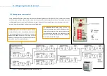
Both the timing relay and the storm control unit must be set up as described on
the next pages. This set
-
up and the settings must be documented!
A storm con-
trol that has not been set
-
up properly provides NO protection at all!
Install all electric components in a protective enclosure. Follow the relevant VDE regula-
tion and legislation.
Under no circumstances may any other parts (fuse, RCCB etc.) be installed into
the wind turbine (wiring diagram depics the entire system
‚
wind turbine
‘)!
Install an AC
-
switch that can enable or disable the AC supply of the system. This switch
can be used to shut
-
off the entire wind turbine, but may only be used every 60 minutes.
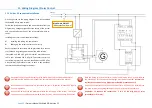
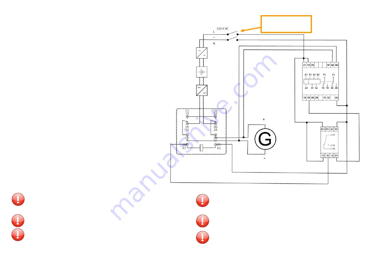
Remember to connect the contacts no. 1 & 3 of the high energy relay
(manufacturer: Schrack).
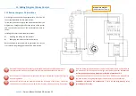
On the right you see the wiring diagram for a 12 or 24 V DC
connected SkyWind NG micro wind turbine.
Follow the instructions exactly and do not deviate from this
diagram. Any changes might affect the safety of the system
and can cause destruction of the wind turbine within se-
conds.
Installing the storm control requires to steps:
A)
Installing and wiring the components
B)
Setting
-
Up the strom control unit correctly
Both steps require accurate work to guarantee for a succes-
sful, safe and long lasting operation of the wind turbine.
Main Switch ON/OFF
(60 Minutes Cool
-
Down)

