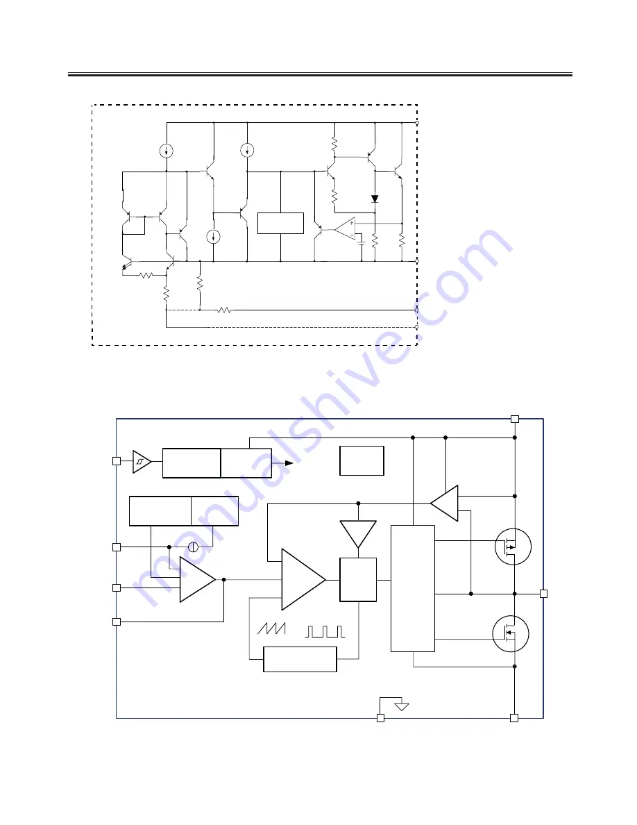
IC Block Diagram
-
U2
(
3.3V/1A 3-TERMINAL POSITIVE VOL TAGEREGULATOR
)
LD1117-3.3 SOT-223
GND (Fixed Output)
ADJ (Adjustable Output)
Thermal
Shutdown
Ou t
+
-
INPUT
OUTPUT
U50
(
1.1V/3A LOW DROPOUT LINEARAR REGULATOR
)
AOZ1051PI SO-8
500kHz
Oscillator
AGND
PGND
VIN
EN
FB
SS
COMP
LX
OTP
Internal
+5V
ILimit
PWM
Control
Logic
5V LDO
Regulator
UVLO
& POR
Softstart
Reference
& Bias
0.8V
SS
5μA
Q1
Q2
PWM
Comp
Level
Shifter
+
FET
Driver
ISen
EAmp
+
–
+
–
+
–
+
Summary of Contents for 8M51B
Page 2: ...Content 2 11 17 18 19 20 21 28 29 45 46 49 50 57...
Page 3: ...LED 8M51B...
Page 5: ...65 120 140 For 32 LED For 42 LED For 47 LED...
Page 6: ...8 8 6...
Page 7: ...40 40 3 2 1 4 2 50 0 5 80 40 3 12000 26inches is 8 ohm 3 3 3 3 DC Voltage PANEL 12 12...
Page 8: ...40 YES 8 6 46 46 NO NO Standard Spanish Standard 20...
Page 9: ...4 2 4 0 40 70 0 40 70 0 40 40 85 Y0 50 30000...
Page 23: ......
Page 24: ...U16 64M X 16 BIT G DIE DDR3 1333 SDRAM FBGA 96...
Page 25: ...U17 128M X 16 BIT G DIE DDR3 1333 SDRAM FBGA 96...
Page 26: ...U8 16MB SPI FLASH SOP 8 U21 2G BIT CMOS NAND EEPROM TSOPI48...
Page 27: ......
Page 28: ...Main PCB Top Bottom Layer...
Page 29: ...Main PCB Top Bottom Layer...
Page 30: ...8M51B Service Adjustment V0 1...


