IC Block Diagram
-
17
-
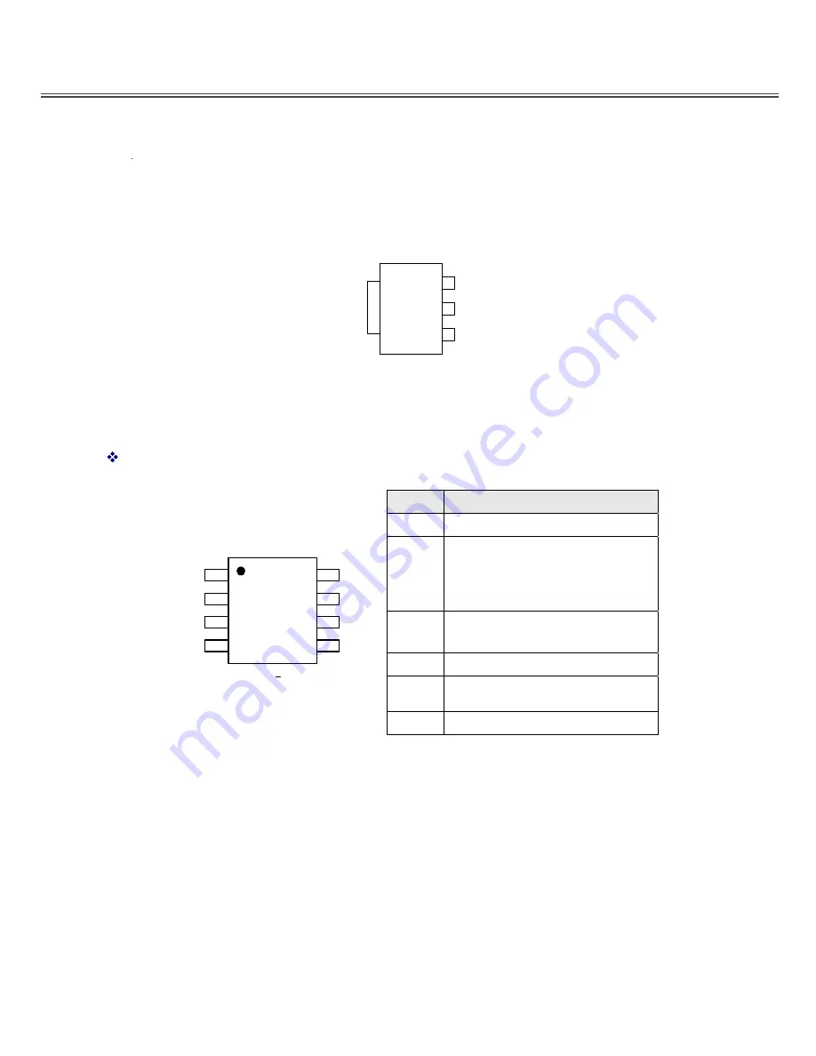
Pin Configurations---AS1117L-ADJ
L Package
(SOT-223)
INPUT
OUTPUT
ADJ/GND
V
OUT
1
2
3
PIN ASSIGNMENT
The package of AX3113 is SOP-8L; the pin assignment is given by:
Name
Description
FB
Feedback pin
EN
Power-off pin
H
Κ
normal operation(Step-down)
L
Κ
Step-down operation stopped
(All circuits deactivated)
OCSET
Add an external resistor to set max
switch output current.
V
CC
IC power supply pin
SW
Switch
pin.
Connect
external
inductor & diode here.
( Top View )
1
2
3
4
8
7
6
5
FB
Ocset
SOP
–
8L
AX3113
Vcc
EN
Vss
Vss
SW
SW
V
SS
GND pin
Summary of Contents for 8M79B Chassis
Page 3: ...3 LCD 8M79B chassis...
Page 5: ...For 42LED For 42LED 5 9800 12500 12500 266 276 9800 280 290 6500 313 329...
Page 6: ...40 40 3 2 1 4 2 50 0 5 80 40 12000 6 24 6...
Page 8: ...8 4...
Page 18: ...IC Block Diagram 18 LM4558 MP1482DS BS IN SW GND SS EN COMP FB 1 2 3 4 8 7 6 5 TOP VIEW...
Page 21: ...IC Block Diagram 21 EN25F32 Figure 2 BLOCK DIAGRAM...
Page 30: ...MAIN PCB TOP 30...
Page 31: ...MAIN PCB BOT 31...
Page 46: ...168P P32EWM K0 Service manual 3 2 2 2 the LED driver of the circuit MICRO ELECTRONICS OZ9967...
Page 51: ...168P P32EWM K0 Service manual 8 3 3 4 The pin description and the voltage...


