11 / 15
Copyright (c) 2009-2013 RoboPeak Team
Copyright (c) 2013-2016 Shanghai Slamtec Co., Ltd.
RPLIDAR A2 Pin Definition and Specification
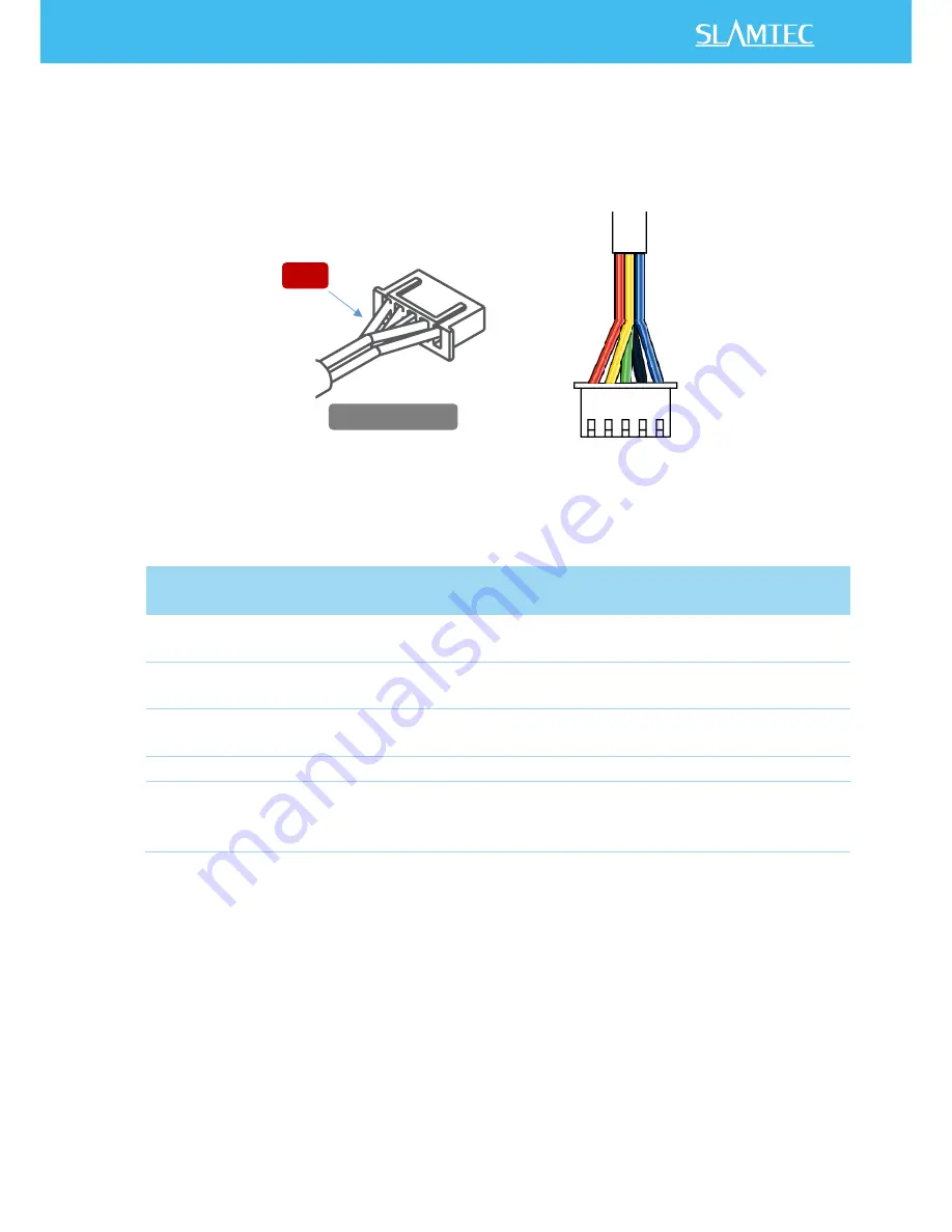
RPLIDAR A2 is using XH2.54-5P specification plug. Please use it with socket that
meet the specification of XH2.54-5P. The detailed pin definition is shown as below:
Figure 3-1 RPLIDAR A2 Pins
Figure 3-2 RPLIDAR Pin Definition and Specification
RPLIDAR A2 uses the one 5V DC power supply for powering the scan motor and
the scan core at the same time. No extra power is required.
With build-in and speed-adjustable motor driver, RPLIDAR A2 can control the
start, the stop and the rotating speed of the motor via the MOTOCTL signal.
o
Reference Design for RPLIDAR development
SDK Introduction and Usage
Color
Signal
name
Type
Description
Minimum Typical Maximum
Red
VCC
Power
Power supply for the whole
RPLIDAR
4.9V
5V
5.5V
Yellow TX
Output
Serial output for RPLIDAR
scan core
0V
3.3V
3.5V
Green RX
Input
Serial input for RPLIDAR scan
core
0V
3.3V
3.5V
Black
GND
Power
GND
0V
0V
0V
Blue
MOTOCTL
Input
(pull
down)
Enable pin for RPLIDAR scan
motor/PWM control signal
(active high)
0V
3.3V
5V
Red
XH2.54-5P
VC
C
TX
RX
GN
D
M
OT
OC
TL


