background image

NOTICE

I   SAFETY

The warranty on this water heater is in effect only when the

water heater is installed and operated in accordance with

these instructions. The manufacturer of this water heater will

not be liable for any injury or property damage resulting

from failure to comply with these instructions.

WARNING!

This water heater must be installed strictly in

accordance with the instructions enclosed, and local electri-

cal, fuel and building codes. It is possible that connections to

the water heater, or the water heater itself may develop

leaks. IT IS THEREFORE IMPERATIVE that the water

heater be installed so that any leakage of the tank or related

water piping is directed to an adequate drain in such a way

that it cannot damage the building, furniture, carpeting, adja-

cent areas, lower floors of the structure or other property

subject to water damage. This is particularly important if the

water heater is installed in a multi-story building, on finished

flooring or carpeted surfaces. SLANT/FIN CORP. CANNOT

BE HELD LIABLE for damage caused by water from the

water heater, pressure relief valve, or related fittings. Closets

without drains and carpeted areas are examples of unsuit-

able locations for any water heater. Select a location as cen-

tralized within the piping system as possible. The heater

should be located in an area not subject to freezing temper-

atures at any time. It is recommended that a suitable drain

pan be installed under the water heater. This pan shall be a

minimum of 50mm (2 in.) deep and have a diameter that is

a minimum of 50mm (2 in.) greater than the diameter of the

water heater. Suitable piping shall connect the drain pan to

a properly operating floor drain.

Relief Valve Requirements

Caution:

To reduce the risk of excessive pressures and

temperatures in this water heater, install temperature

and pressure protective equipment required by local

codes. It should be no less than a combination temperature

and pressure relief valve certified by a nationally

recognized testing laboratory that maintains periodic

inspection of production of listed equipment or materials,

as meeting the latest edition of ANSI Z21.22:

Requirements for Relief Valves and Automatic Gas

Shut-off Devices for Hot Water Supply Systems. This

valve must be marked with a maximum set pressure not

to exceed the marked MAXIMUM working pressure of the

water heater (150 PSI). Install the valve into an opening

provided and marked for this purpose in the water

heater, and orient it or provide tubing so that any

discharge from the valve will exit only within 6 inches

above, or any distance below the structural floor and

cannot contact any live electrical part. The discharge

opening must not be blocked or reduced in size under

any circumstances. The end of the relief pipe opening

should terminate near a floor drain or other suitable

location not subject to blocking or freezing. DO NOT

thread, plug or cap the relief pipe opening.

2

INDIRECT FIRED WATER TANK

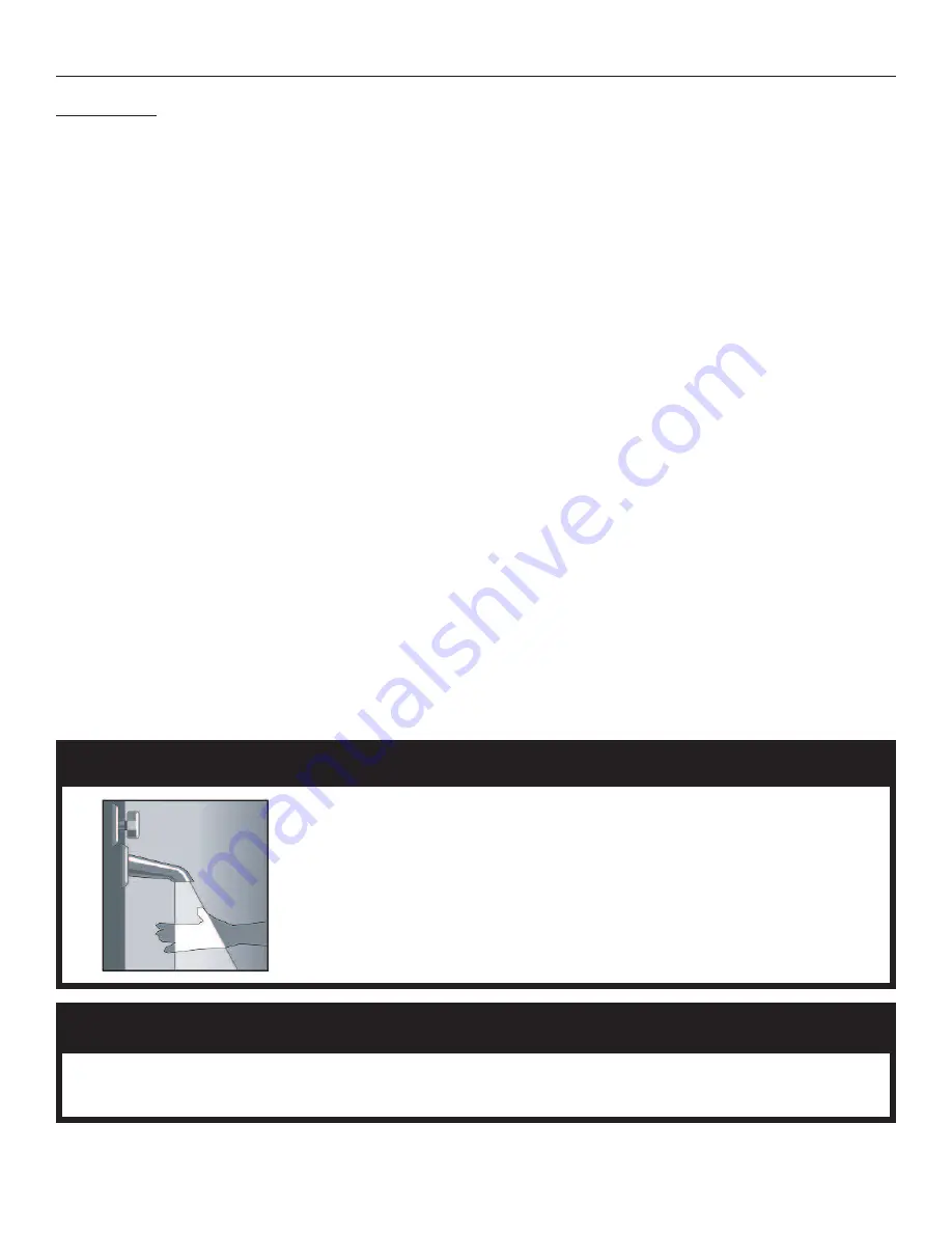
Water temperatures over 125ºF can cause severe burns instantly,

or death from scalds.

Children, disabled, and elderly are at the highest risk of being scalded.

See instruction manual before setting temperature at water heater.

Feel water before bathing or showering.

Temperature limiting valves are available, see manual.

The Indirect-fired water heater is deemed to be used in a "commercial setting" if at any time the unit is oper-

ated at a temperature over 150ºF. Refer to warranty for additional information.

DANGER

r

!

r

!

HOT

BURN


Summary of Contents for HWT-120

Page 1: ...valve of the proper rating for the heater tank size is required Install a tempering device such as a mixing valve on hot water piping which feeds areas where high temperature water is not demanded When servicing this installation make sure drain con nections are tight and drain hose is directed away from all persons or areas where injury or damage can occur Contents Page I Safety 2 II Product Sele...

Page 2: ...he drain pan to a properly operating floor drain Relief Valve Requirements Caution To reduce the risk of excessive pressures and temperatures in this water heater install temperature and pressure protective equipment required by local codes It should be no less than a combination temperature and pressure relief valve certified by a nationally recognized testing laboratory that maintains periodic i...

Page 3: ...otential maximum usage Estimate of Peak Domestic Hot Water Usage Shower 20 x______________________ x_______________________ Bath 20 x______________________ x_______________________ Shaving 2 x______________________ x_______________________ Hands and Face Washing 4 x______________________ x_______________________ Hair Shampoo 4 x______________________ x_______________________ Hand Dish Washing 4 x_...

Page 4: ...35 54 5 8 42 20 20 40 1 4 33 7 8 10 7 16 10 7 16 10 7 8 13 8 7 8 8 7 8 10 1 4 8 7 8 14 14 26 26 116 118 232 333 124 143 243 355 449 576 737 1324 PHYSICAL SPECIFICATIONS CONNECTIONS NOTES 1 All fittings are female NPT thread connections except for domestic hot and cold on the HWT 120 2 HWT 120 supplied with adapter to increase from 1 male to 1 1 4 female for domestic hot and cold 3 HWT 120 has insp...

Page 5: ...the vicinity of this or any other appliance Controls on this appliance could ignite vapors causing an explosion PIPING 1 General a All plumbing must be in accordance with the requirements of the authority having jurisdiction b Use both thread tape and pipe dope on all mechanical connections c Zone valve if used and circulator must be sized to provide minimum flow rate specified in the table to the...

Page 6: ...Breaker Slant Fin recommends that a vacuum breaker be installed on the domestic piping to the heater The vacuum breaker protects the heater in the event that tank pressure falls below atmospheric pressure Temperature Pressure Relief Valve T P A T P is required on all heaters Install a T P valve long element type into the separate tapping designated for the T P Install temperature and pressure prot...

Page 7: ...K CONTROL TEMP PRESSURE RELIEF VALVE BALL VALVE CIRCULATOR ZONE VALVE CHECK VALVE DRAIN VALVE HOT WATER BOILER HOT WATER BOILER MULTIPLE TANK INSTALLATION IV INSTALLATION PIPING cont d PIPING TANK INSTALLATION Notes Thermal Expansion Tank is required whenever a backflow preventer or no return valve is present in the system Locate the Thermal Expansion Tank on the Domestic Cold water line between t...

Page 8: ... and C and observe boiler water level at the gauge glass making sure that it remains at its original level Fill the potable water side of the tank and purge air from tank by opening a hot water faucet When the power is switched on the tank aquastat will turn on pump F and when the temperature of the boiler falls below the set point the boiler will fire A A B C E D F G I H Water level STEAM BOILER ...

Page 9: ...n much the same way as a thermostat When the temperature falls inside the tank the set of contacts make close and when the temperature rises the contacts break open The aquastat should be tied into the boiler system and controls When the tank calls for heat the aquastat contacts close and signal the boiler controls allowing the boiler to maintain temperature and proper operation of the tank circul...

Page 10: ...zone 6 is switched to the priority setting and is actuated all other zones will stop operation until zone 6 is satisfied When zone 6 is not switched to priority all zones will oper ate independently Jumper Placement REMOVE the jumper between terminals ZC and ZR Connect terminal ZC to ZC terminal on the aquastat control Connect terminal ZR to ZR terminal on the aquastat control Confirm polarity is ...

Page 11: ...EMP CONTROL I INDIRECT TANK CIRCULATOR Operation When any thermostat calls for heat the appropriate circulator is energized and the isolated end switch X and X will start the boiler Priority Operation When zone 6 is switched to the priority setting and is actuated all other zones will stop operation until zone 6 is satisfied When zone 6 is not switched to priority all zones will oper ate independe...

Page 12: ...12 INDIRECT FIRED WATER TANK V WIRING cont d Figure 5 Wiring to a gas boiler with circulator zoning Figure 6 Wiring to an oil boiler with circulator zoning ...

Page 13: ...to simplify the wiring and provide priority on domestic hot water demand Zone valve zoning wiring See Fig 7 8 a Components must be wired to ensure that only the zone valve for each zone is powered on a demand for supply water from zone and that the circulator is powered on a demand from any zone b The transformer used to power the zone valves must be sized for the load of all the zone valves in sy...

Page 14: ...ve 3 Open the household hot water taps 4 Attach a hose to the drain valve located at the bottom of the heater and allow the heater to drain 5 Unscrew the anodes Two shiny 1 1 4 Hex Heads on front of tank EXAMINE THE ANODES AND REPLACE IF THE DIAME TER IS LESS THAN 40 inches 6 Replacement of the Anodes The use or P T F E tape is recommended to ensure watertight connection of the anodes Failure to i...

Page 15: ...ater having a defect or malfunction that results in a water leak from the outside jacket inner tank or heat exchanger as a result of normal use and service It is expressly agreed between Slant Fin Corp and the original residential purchaser that repair or replacement is the exclusive and sole remedy of the original purchaser Any claim under this warranty must be verified by an authorized Slant Fin...

Page 16: ...tion or defects and maintenance in the ordinary course 13 Components of an indirect fired water heater which are not manufactured expressly for Slant Fin Corp such components are subject only to those warranties if any given by their manufacturers Slant Fin Corp does not adopt and has no responsibility for those warranties 14 Any tank that does not have installed a new temperature and pressure rel...

Reviews: