background image

2

Sentinel

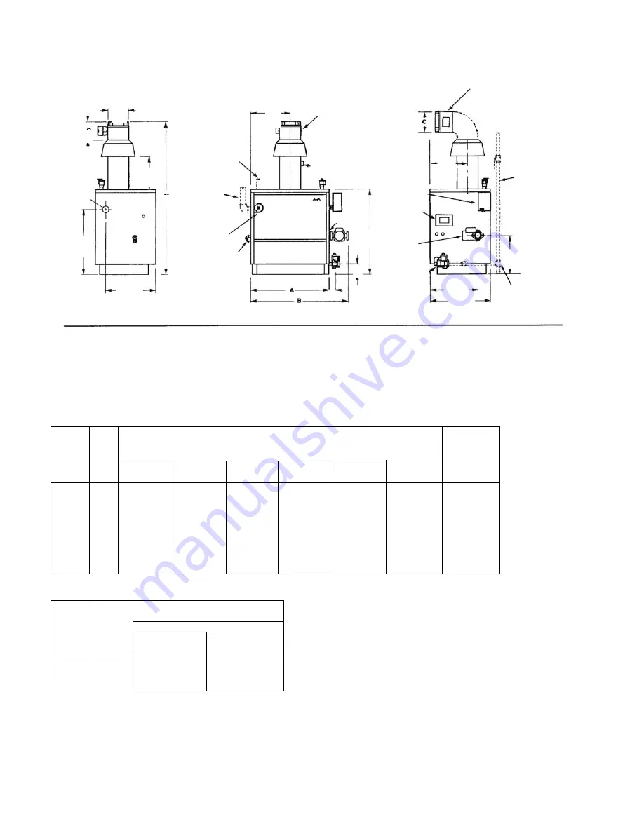
Dimensions
MODEL SE-70 to SE-245

SE 70

3

283

11

1

/

8

448

17

5

/

8

102

4

1289

50

3

/

4

143

5

5

/

8

152

6

113

250

SE 105

4

359

14

1

/

8

524

20

5

/

8

127

5

1311

51

5

/

8

181

7

1

/

8

152

6

141

310

SE 140

5

435

17

1

/

8

600

23

5

/

8

127

5

1311

51

5

/

8

219

8

5

/

8

152

6

166

365

SE 175

6

511

20

1

/

8

676

26

5

/

8

152

6

1356

53

3

/

8

257

10

1

/

8

165

6

1

/

2

193

425

SE 210

7

587

23

1

/

8

752

29

5

/

8

178

7

1376

54

3

/

16

295

11

5

/

8

179

7

1

/

16

220

485

SE 245

8

664

26

1

/

8

829

32

5

/

8

178

7

1376

54

3

/

16

333

13

1

/

8

179

7

1

/

16

247

545

Boiler
Model

Gas

Type

610m – 1220m

(2000' – 4000')

1220m – 1372m

(4000' – 4500')

Orifice

Size for

Sea

Level

Orifice Sizes for High Altitudes

Reduce output 10%

Elevation – Meters (Feet)

No. of

Sect.

Dimensions

A

mm

in.

B

mm

in.

D

mm

in.

E

mm

in.

G

mm

in.

kg

lb

C

mm

in.

Approx.

Total Wt.

Full of Water

Natural

47

48

Propane

56

56

CHIMNEY RECOMMENDATIONS
HEIGHT: 4.6 m (15 ft.) (minimum) from draft hood skirt to top of chimney.
INSIDE DIAMETER: Same as dimension C (or larger).
NOTE: Larger chimney may be required if two or more boilers or a boiler and another appliance are vented to a
 single chimney.

Orifice indicated for sea level above are factory installed in
boiler unless otherwise specified by the local authority. See
Section “III” on page 15 for burner input adjustment.

1-1/2" FPT

Supply

419 mm
(16-1/2")

552 mm (21-3/4")

3/4" 

to air eliminating

system (by others)

Vent Damper*

(shown vertically

)

Vent Damper*

(shown horizontally

)

Sediment Trap

(required)

High Limit

Control

Ignition
Control

Blocked Vent

Safety Switch

3/4" Drain

Left End View

Front View

Right End View

1-1/2"

FPT

Return

722 mm

(28-7/16")

276 mm
(10-7/8")

Circulator:

1-1/4" Circ. Flange

1-1/2" Return

Tapping

Combination 

Gas Valve

[gas tapping 

1/2"]

397 mm
(15-5/8")

502 mm
(19-3/4")

324 mm (12-3/4")

Install manual gas main

shutoff valve 1524 mm

(5 ft.)  above floor, when

required by local code.

Install sediment trap

and connect with

ground joint union.

Dotted piping by

installing contractor.

Note: Height dimension increases by 44 mm (1 3/4") when combustible floor kit is used.
* Vent damper may be installed horizontally on all models with use of a vent elbow. For more information, see Figure 2, page 5.

G

D

C

E

279 mm

(11")

Rollout Safety Switch

(behind front panel)

Supply Piping 

(by others)

Pressure/Temp

. Gauge

76 mm 

(3")

3

49
57

Summary of Contents for SENTINEL

Page 1: ... READING THE INSTALLATION INSTRUCTIONS The installation must conform to the requirements of the authority having jurisdiction or in the absence of such requirements to the National Fuel Gas Code ANSI Z2231 latest edition or CSA B 149 1 latest edition for natural gas and propane The installation must also conform to the additional requirements in this Slant Fin Instruction Book In addition where re...

Page 2: ...ther appliance are vented to a single chimney Orifice indicated for sea level above are factory installed in boiler unless otherwise specified by the local authority See Section III on page 15 for burner input adjustment 1 1 2 FPT Supply 419 mm 16 1 2 552 mm 21 3 4 3 4 to air eliminating system by others Vent Damper shown vertically Vent Damper shown horizontally Sediment Trap required High Limit ...

Page 3: ... etc during appliance operation and service circulator replace ment condensate trap control replacement etc BOILER FOUNDATION A Provide a solid level foundation capable of supporting the weight of the boiler filled with water and extending at least 51 mm 2 past the jacket on all sides See dimensions of boiler page 2 B For installation on non combustible floors only The Com bustible Floor Kit part ...

Page 4: ...s utility local building codes and other authorities having jurisdiction If a masonry chimney is exposed to the outdoors on one or more sides below the roof line exterior chimney ONE of the following options apply 1 Chimney must be re lined with an approved metallic liner When this is done the chimney will be considered NOT exposed to the outdoors and the requirements for NON exposed chimneys and ...

Page 5: ...od outlet and the connec tor to the outdoor chimney or vent as close to the draft hood as practicable and without modification of the draft hood or the damper See figures 1 and 2 6 The inlet size of the vent damper must be the same nominal trade size as the outlet of the draft hood 7 This device must be located in a venting system or section of a venting system so that it serves only the single ap...

Page 6: ...ther end of the flexible metal conduit has a small molex plug and a 90 degree metal conduit connector Route the molex receptacle through the conduit bracket on the vent damper Place the harness receptacle into the damper plug Securely fasten the harness conduit con nector to the conduit bracket by carefully pushing it into the hole in the bracket 4 Restore electrical power and turn on gas supply C...

Page 7: ...electrical source is utilized the boiler when installed must be electrically grounded in accordance with the requirements of the authority having jurisdiction or in absence of such requirements with the Cana dian Electric Code CSA C22 1 Part 1 latest edition C Basic control wiring diagrams are supplied Other control systems may be factory sup plied see User s Information Manual and Instructions pa...

Page 8: ...8 Sentinel Figure 8 Multizoning of Sentinel boilers pump zoning system using R845A relay Figure 9 Multizoning of Sentinel boiler 2 zone system pump zoning system using R882A B relays ...

Page 9: ... same function THIS OVERRIDE MUST NOT BE USED UNLESS AT LEAST ONE OF THE FOLLOWING CONDITONS IS TRUE r e t a w r e l i o b e h t s e c u d e r t a h t d e l l a t s n i s i m e t s y s t n e m e g a n a m y g r e n e l a n r e t x e n A temperature as the heating load decreases g n i t a e h e c a p s y n a r o f d e s u t o n s i r e l i o b s i h T r e t a e r g r o H B M 0 0 3 w k 8 8 f o t u p...

Page 10: ...AIN BURNERS OFF VENT DAMPER CLOSES CIRCULATOR OFF SYSTEM GOES TO STANDBY SPARK GENERATOR MODULE POWERED S8600F OR S8600M IGNITION SPARK STARTS AND PILOT VALVE OPERATOR OPENS S8670E IGNITION SPARK AND PILOT VALVE OPERATOR DELAYED FOR 30 70 SECONDS L P PROPANE GAS S8600M and S8670E IGNITION TRIAL CONTINUES FOR 90 SECONDS AFTER TRIAL FOR IGNITION SYSTEM SHUTS OFF AFTER 5 MINUTES MODULE RE INSTATES TR...

Page 11: ... push and hold the but ton a second time for 20 seconds The display will read Pur OFF SETTING THE CONTROL At initial start up with the Economy Feature active the control establishes a 63 C 145 F target temperature To test the high limit shut off function the Economy Dial must be turned to OFF Once tested restore the Economy setting If the heating demand is high the target will increase over time t...

Page 12: ...l Targeting Works on page 4 for more information zECONOMY TARGET When the Economy feature is active the Fuel Smart HydroStat continually sets target temperatures below the high limit setting to maximize fuel efficiency When the boiler water reaches the target temperature the LED illuminates and the burner will shut down The boiler water will continue to cir culate and heat the house as long as the...

Page 13: ...nd should be provided If the boiler is not near an outside wall air may be ducted to it from outside wall openings Provisions for combustion and ventilation air must be made in accordance with section 5 3 Air for Combustion and Ventila tion of the National Fuel Gas Code ANSI Z2231 latest edition or CSA B 149 1 latest edition for natural gas and propane or applicable provisions of the local buildin...

Page 14: ...ER PIPING I CIRCULATING SYSTEMS A Hot water heating systems include a water circulating pump which may be mounted on the supply or return side of the boiler based on system design See figure 5 II AIR CONTROL SYSTEM A DIAPHRAGM EXPANSION TANKS are used to control system pressure in an AIR ELIMINATING SYSTEM an automatic air vent is used to REMOVE air from the sys tem water See figure 9 If system pr...

Page 15: ...NSI Z223 1 latest edition or CSA B149 1 00 for natural gas and propane does NOT permit firing at a higher input rate than the input rate indicated on the boiler rating plate in order to avoid hazardous conditions such as explosion or carbon monoxide poisoning b Poor higher heating value of gas is causing the actual input to be substantially lower than the rating plate indication Higher heating val...

Page 16: ... gauge 2 Air control system noise and air binding in system should be corrected 3 Water lines slightest leaks should be corrected 4 Low water cutoff for operation see instructions fur nished with unit 2 WATER LEVEL CHECK DURING HEATING SEASON A Check water pressure regularly and add water slowly to system when needed If much water is added venting may be necessary B Regular loss of water from wate...

Page 17: ...hen system water glycol solution is in contact with a potable water vessel as with a tankless heater PROPYLENE GLYCOL is used in the quick freeze food industry it is practically non toxic Its use may be permitted when tankless heaters are used When anti freeze must be used inhibited propylene glycol is recommended Useful information on the characteristics mixing proportions etc of glycol in heatin...

Page 18: ...zontal run of smokepipe 4 Inadequate chimney or venting system REMEDY 1 Check clean re light See instructions 2 Open gas valve s 3 Close switch 4 Replace fuse 5 Check control Clean contacts or replace control 6 Repair or replace 7 Replace transformer 8 Check clean and reinstall 9 Check with test light and correct 10 Check and correct in accordance with wiring diagrams included with appliance instr...

Page 19: ...t so appliance will operate continuously e Test for spillage at the draft hood relief opening after 5 min utes of main burner operation Use the flame of a match or candle or smoke from a cigarette cigar or pipe f After it has been determined that each appliance remain ing connected to the common venting system properly vents when tested as outlined above return doors win dows exhaust fans fireplac...

Page 20: ...ed from a well This accumulation creates an insulating layer that drastically affects boiler efficiency by reducing the transmission of heat through this primary transfer surface and causes extreme metal temperatures that eventually crack the heat exchanger RECOMMENDATIONS On all installations in hard water areas 1 The system should be thoroughly inspected for leaks which must be repaired however ...

Reviews: