24
3.
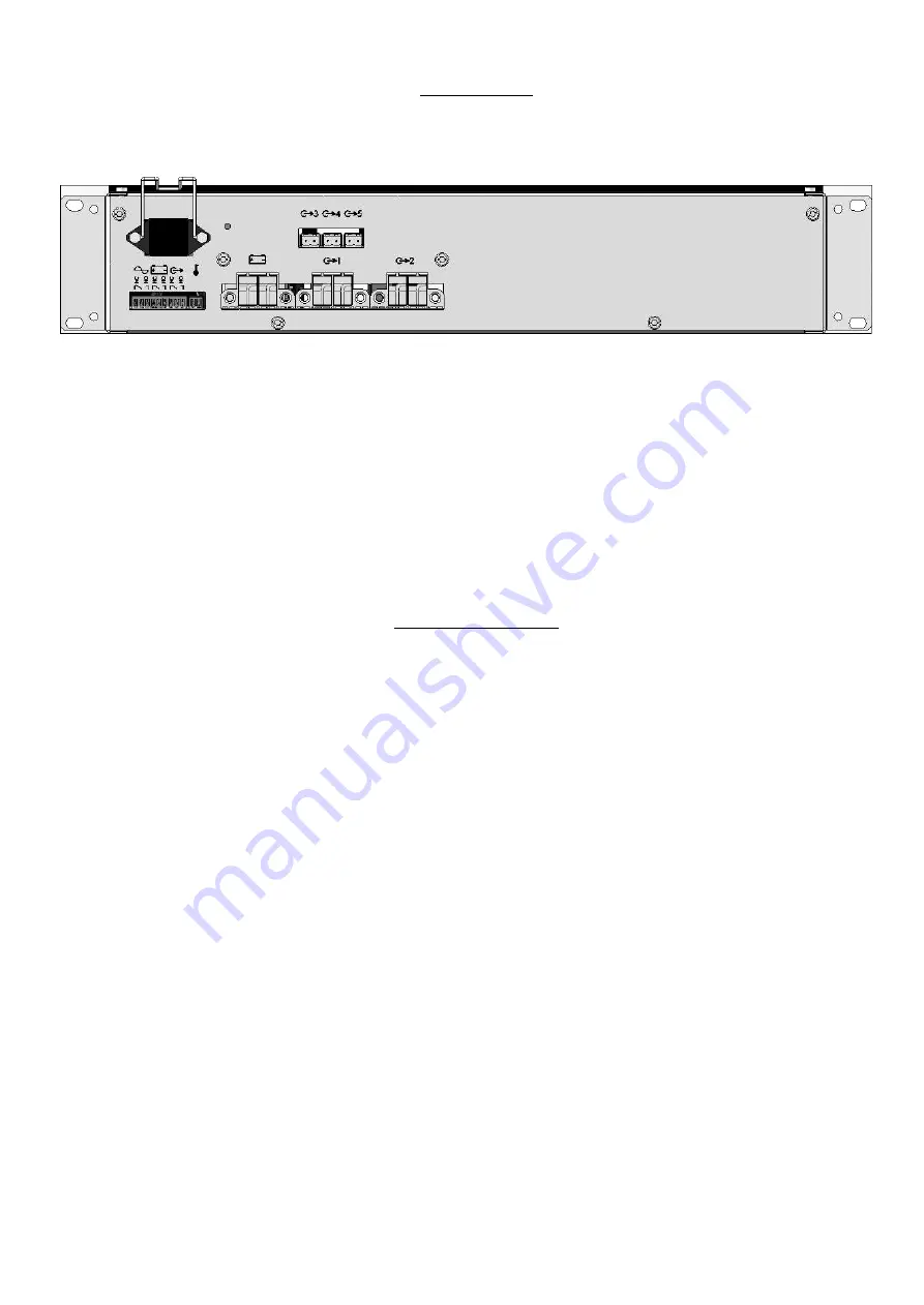
Connection
3.1.
Connection diagram
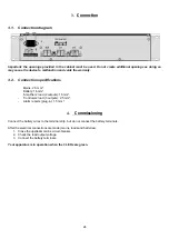
Important: the openings provided in the cabinet must be used. Do not create additional openings as doing so
may casue the device to malfunction and voids the warranty.
3.2.
Connection specifications
-
Mains: 2.5 mm².
-
Battery: 16 mm².
-
‘Amplifiers’ load (2 outputs): 16 mm².
-
‘Controlers’ load (3 outputs): 2.5 mm².
-
Alarm reports (plug-in): 1.5 mm².
4.
Commissioning
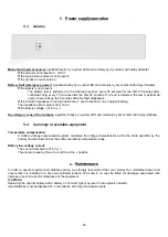
Connect the battery wires to the terminal strip, but do not connect the battery terminals.
After the electrical connections are made (mains, loads and batteries).
1. Close the upstream mains circuit-breaker.
2. Check the load output voltage.
3. Connect the battery terminals.
Your apparatus is in operation when the 3 LEDs are green.


