Issue 10 (01/10/2004) Page 223 of 258
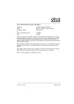
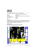
19.1.9 SI 990401 Attenuated alarm sounder for the 12/24V voltage monitor.
Introduction
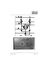
The silk screening on the A0738/02 board is incorrect for transistors T1 and T2. In production
this has resulted in both transistors fitted with the emmiter and collector transposed. In this
configuration there may not be enough current to drive the alarm sounder. During testing of
the ventilator, if the alarm would not reliably sound, a modification was made to reduce the
resistor R33 from 10k0 to 8k2. This provides enough current for the alarm sounder to work.
Now the transistors are fitted in production as originally intended so that they are
working in a more conventional manner. That is, to fit them in the opposite way to that indi-
cated on the silk screen.
All units manufactured to date and currently in service have passed their final test and were
functional on leaving the factory. There is no reason to suppose that any of the operating
parameters for this circuit would have changed or that device failure would have occured since
the reverse configuration does not have the potential to damage the components.Therefore
units in the field shall continue to operate reliably and it is not necessary to modify them. How-
ever service personnel should be made aware of the new production directive and how it will
result in T1 and T2 apparently being fitted the wrong way round.
Subject
:Slightly attenuated alarm sounder for the 12/24V voltage
monitor.
Equipment
:SLE2000HFO/HFO ‘plus’
Serial Numbers
:All SLE2000HFO ventilators prior to serial numbers
9H0301(99)
All SLE2000HFO “plus” ventilators prior to serial numbers
9J0305(99)
Service Information Number
:Si 990401
Change Note Ref
:CN 0520
Date
:13/04/99
Summary of Contents for 2000 HFO
Page 1: ...Issue 10 SLE 2000 HFO Ventilator Service manual High Frequency Oscillatory Ventilator 0120 ...
Page 8: ...Page 8 of 258 Issue 10 01 10 2004 This page is intentionally blank ...
Page 9: ...Issue 10 01 10 2004 Page 9 of 258 Introduction ...
Page 11: ...Issue 10 01 10 2004 Page 11 of 258 Ventilator Control Description ...
Page 17: ...Issue 10 01 10 2004 Page 17 of 258 Access to Internal Components ...
Page 26: ...Page 26 of 258 Issue 10 01 10 2004 This page is intentionally blank ...
Page 27: ...Issue 10 01 10 2004 Page 27 of 258 Maintenance ...
Page 35: ...Issue 10 01 10 2004 Page 35 of 258 Overhual ...
Page 37: ...Issue 10 01 10 2004 Page 37 of 258 Exchanging a Pneumatic Unit ...
Page 39: ...Issue 10 01 10 2004 Page 39 of 258 Setup and Calibration ...
Page 57: ...Issue 10 01 10 2004 Page 57 of 258 Technical Specification ...
Page 73: ...Issue 10 01 10 2004 Page 73 of 258 Troubleshooting Chart ...
Page 78: ...Page 78 of 258 Issue 10 01 10 2004 This page is intentionally blank ...
Page 79: ...Issue 10 01 10 2004 Page 79 of 258 Circuit Details ...
Page 80: ...Page 80 of 258 Issue 10 01 10 2004 17 Circuit Details 17 1 AS A0700 02 Display Board Assembly ...
Page 81: ...Issue 10 01 10 2004 Page 81 of 258 17 1 1 CD A0700 02 Display Board Circuit Diagram ...
Page 83: ...Issue 10 01 10 2004 Page 83 of 258 17 2 AS A0701 02 LED PCB Assembly ...
Page 84: ...Page 84 of 258 Issue 10 01 10 2004 17 2 1 CD A0701 02 LED Board Circuit Diagram ...
Page 87: ...Issue 10 01 10 2004 Page 87 of 258 17 3 AS A0702 04 CPU PCB Issue 2 Sheet 1 of 2 ...
Page 88: ...Page 88 of 258 Issue 10 01 10 2004 17 3 1 AS A0702 04 CPU PCB Issue 1 Sheet 2 of 2 ...
Page 93: ...Issue 10 01 10 2004 Page 93 of 258 17 4 AS A0702 04 CPU PCB Issue 3 Sheet 1 of 2 ...
Page 94: ...Page 94 of 258 Issue 10 01 10 2004 17 4 1 AS A0702 04 CPU PCB Issue 3 Sheet 2 of 2 ...
Page 99: ...Issue 10 01 10 2004 Page 99 of 258 17 5 AS A0702 04 CPU PCB Issue 5 Sheet 1 of 2 ...
Page 100: ...Page 100 of 258 Issue 10 01 10 2004 17 5 1 AS A0702 04 CPU PCB Issue 5 Sheet 2 of 2 ...
Page 126: ...Page 126 of 258 Issue 10 01 10 2004 17 10 AS A0737 01 Bargraph Display PCB Assembly ...
Page 127: ...Issue 10 01 10 2004 Page 127 of 258 17 10 1 CD A0737 01 Bargraph Display PCB Circuit Diagram ...
Page 129: ...Issue 10 01 10 2004 Page 129 of 258 17 11 AS A0738 02 Alarm PCB Assembly ...
Page 130: ...Page 130 of 258 Issue 10 01 10 2004 17 11 1 CD A0738 02 Alarm PCB Circuit Diagram ...
Page 139: ...Issue 10 01 10 2004 Page 139 of 258 17 13 AS A0739 02 Motor Drive PCB Issue 3 Revision C ...
Page 143: ...Issue 10 01 10 2004 Page 143 of 258 17 14 AS A0756 HFO Motor Start Up PCB Issue 2 ...
Page 145: ...Issue 10 01 10 2004 Page 145 of 258 17 15 AS A0745 Pressure Drift Monitor Board Issue 1 ...
Page 147: ...Issue 10 01 10 2004 Page 147 of 258 17 16 AS A0745 Pressure Drift Monitor Board Issue 2 ...
Page 150: ...Page 150 of 258 Issue 10 01 10 2004 17 17 Serial Interface Option CD A0702 03 ...
Page 153: ...Issue 10 01 10 2004 Page 153 of 258 17 19 Front Panel ...
Page 154: ...Page 154 of 258 Issue 10 01 10 2004 17 20 SK0057 Power Supply Wiring Diagram ...
Page 156: ...Page 156 of 258 Issue 10 01 10 2004 17 22 Electronic Chassis Sheet 1 of 2 ...
Page 157: ...Issue 10 01 10 2004 Page 157 of 258 17 22 1 Electronic Chassis Sheet 2 of 2 ...
Page 186: ...Page 186 of 258 Issue 10 01 10 2004 This page is intentionally blank ...
Page 189: ...Page 189 of 258 CD A0702 04 Issue 2 ...
Page 190: ...Page 190 of 258 ...
Page 191: ...Page 191 of 258 CD A0702 04 Issue 3 ...
Page 192: ...Page 192 of 258 ...
Page 193: ...Page 193 of 258 CD A0702 04 Issue 4 ...
Page 194: ...Page 194 of 258 ...
Page 195: ...Page 195 of 258 CD A0736 03 Issue 2 Note Please check the revision status of the main board ...
Page 196: ...Page 196 of 258 ...
Page 197: ...Page 197 of 258 CD A0736 03 issue 3 Note Please check the revision status of the main board ...
Page 198: ...Page 198 of 258 ...
Page 199: ...Page 199 of 258 CD A0736 03 issue 4 Note Please check the revision status of the main board ...
Page 200: ...Page 200 of 258 ...
Page 201: ...Page 201 of 258 CD A0736 03 issue 5 Note Please check the revision status of the main board ...
Page 202: ...Page 202 of 258 ...
Page 203: ...Page 203 of 258 CD W0308 ...
Page 204: ...Page 204 of 258 ...
Page 205: ...Issue 10 01 10 2004 Page 205 of 258 Service Information and Technical Bulletins ...
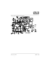
Page 221: ...Issue 10 01 10 2004 Page 221 of 258 The pneumatic circuit diagram is shown here ...
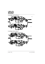
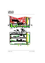
Page 228: ...Page 228 of 258 Issue 10 01 10 2004 Figure 4b ...
Page 231: ...Issue 10 01 10 2004 Page 231 of 258 ...
Page 237: ...Issue 10 01 10 2004 Page 237 of 258 100nf ...
Page 258: ......

