Issue 10 (01/10/2004) Page 97 of 258
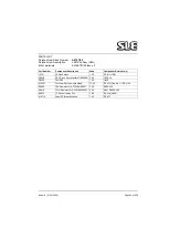
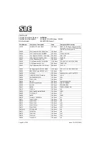
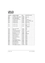
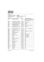
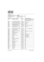
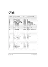
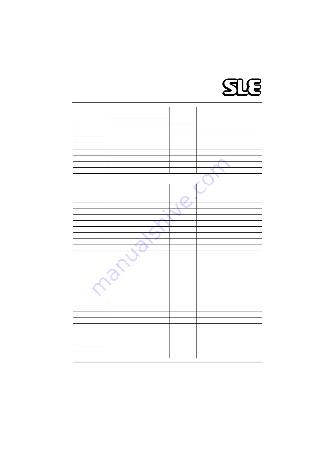
D0580
TLC555CP
1 00 Each
Ull
D0581
LMC660AIN
2 00 Each
U13,U202
D0584
CD40106BE
1 00 Each
U200
D0636
IRLU110 power MOSFET,TO-251
1 00 Each
Q4
D0638
ZTX450Each
1 00 Each
Q3
D0644/01
P80C32EBPN 8-bit CMOS CPU
1 00 Each
U14
M0626
Jumper Link
1 00 Each
ITEM 5
M0660
Pad Adhesive double sided
1 00 Each
ITEM 15 (XL1
M0718
Label, PCB Identifieation
1 00 Each
ITEM 17
N2176
Sensor SXOlDN (Sensym only)
1 00 Each
PTR2
If N2176 is not Pre-Fixed with M on component then R501 becomes 33K(PT No R0473) & U500 becomes
LM358(PT No D0288)
N2521
Pressure Transducer 143SCOlD
1 00 Each
PTR1
00227
Relay W172DIP-5 5V DC
1 00 Each
RL1
P0230
DIN41612 64 Way 90 deg Plug
1 00 Each
PLB
P0464
12way P C B Header Straight
0 25 Each
LK1
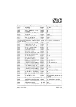
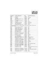
R0224
30K Resistor 0 25W 1%
1 00 Each
R34
R0226
110K Resistor 1% 0.25W
1.00 Each
R208
R0228
8K2 1% 50PPM 0.25W
1.00 Each
R32
R0233
4K7 Resistor 1* 0.25W 50PPM MF
1.00 Each
R22
R0268
5K1 Resistor 1* 0.25W SMA0207
1.00 Each
R36
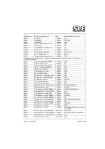
R0349
24K Resistor 0.25W 1%
2.00 Each
R24,R39
R0350
1K x 8 Resistor Network
1.00 Each
RU2
R0351
10K x 8 Resistor Network
1.00 Each
RU1
R0416
150R Resistor 1% 0.25W SMA0207
7.00 Each
R25-R29,R509,R511
R0428
470R Resistor 1% 0.25W
2.00 Each
R41,R60
R0436
1.0K Resistor 1% 0.25W SMA0207
6.00 Each
R12,R30,R31,R205-R207
R0445
2K49 Resistor 1% 0.25W SMA0207
1.00 Each
R23
R0449
3.32K Resistor 1% 0.25W SMA
2.00 Each
R35,R37
R0451
3.92K Resistor 1% 0.25W SMA020
2.00 Each
R38,R504
R0456
5.6K Resistor 1% 0.25W SMA0207
1.00 Each
R21
R0463
10K Resistor 1% 0 25W SMA0207
7.00 Each
R18,19,33,42,43,R507, R508
R0467
15K Resistor 1% 0.25W SMA0207
1.00 Each
R44
R0469
22.1K Resistor 1% 0.25W SMA020
2.00 Each
R40,R204
R0470
23.7K Resistor 1% 0.25W
1.00 Each
R500
R0473
33K Resistor 1% 0.25W
1.00 Each
R501=Pt No.R0467 when pre-fix is not
'S' for PTR2
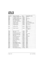
R0479
47K Resistor 1% 0.25W SMA0207
4.00 Each
R1,3,4,R45
R0486
100K Resistor 1% 0.25W SMA0207
7.00 Each
R13,201,202,209,210,R502,R503
R0496
470K Resistor 1% 0.25W SMA0207
1.00 Each
R14
R0499
750K Resistor 1% 0.25W
1.00 Each
R203
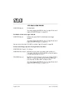
Part Number
Component Description
Used
Component Reference(s)
Summary of Contents for 2000 HFO
Page 1: ...Issue 10 SLE 2000 HFO Ventilator Service manual High Frequency Oscillatory Ventilator 0120 ...
Page 8: ...Page 8 of 258 Issue 10 01 10 2004 This page is intentionally blank ...
Page 9: ...Issue 10 01 10 2004 Page 9 of 258 Introduction ...
Page 11: ...Issue 10 01 10 2004 Page 11 of 258 Ventilator Control Description ...
Page 17: ...Issue 10 01 10 2004 Page 17 of 258 Access to Internal Components ...
Page 26: ...Page 26 of 258 Issue 10 01 10 2004 This page is intentionally blank ...
Page 27: ...Issue 10 01 10 2004 Page 27 of 258 Maintenance ...
Page 35: ...Issue 10 01 10 2004 Page 35 of 258 Overhual ...
Page 37: ...Issue 10 01 10 2004 Page 37 of 258 Exchanging a Pneumatic Unit ...
Page 39: ...Issue 10 01 10 2004 Page 39 of 258 Setup and Calibration ...
Page 57: ...Issue 10 01 10 2004 Page 57 of 258 Technical Specification ...
Page 73: ...Issue 10 01 10 2004 Page 73 of 258 Troubleshooting Chart ...
Page 78: ...Page 78 of 258 Issue 10 01 10 2004 This page is intentionally blank ...
Page 79: ...Issue 10 01 10 2004 Page 79 of 258 Circuit Details ...
Page 80: ...Page 80 of 258 Issue 10 01 10 2004 17 Circuit Details 17 1 AS A0700 02 Display Board Assembly ...
Page 81: ...Issue 10 01 10 2004 Page 81 of 258 17 1 1 CD A0700 02 Display Board Circuit Diagram ...
Page 83: ...Issue 10 01 10 2004 Page 83 of 258 17 2 AS A0701 02 LED PCB Assembly ...
Page 84: ...Page 84 of 258 Issue 10 01 10 2004 17 2 1 CD A0701 02 LED Board Circuit Diagram ...
Page 87: ...Issue 10 01 10 2004 Page 87 of 258 17 3 AS A0702 04 CPU PCB Issue 2 Sheet 1 of 2 ...
Page 88: ...Page 88 of 258 Issue 10 01 10 2004 17 3 1 AS A0702 04 CPU PCB Issue 1 Sheet 2 of 2 ...
Page 93: ...Issue 10 01 10 2004 Page 93 of 258 17 4 AS A0702 04 CPU PCB Issue 3 Sheet 1 of 2 ...
Page 94: ...Page 94 of 258 Issue 10 01 10 2004 17 4 1 AS A0702 04 CPU PCB Issue 3 Sheet 2 of 2 ...
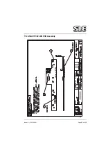
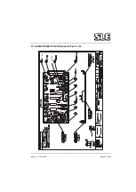
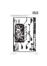
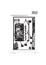
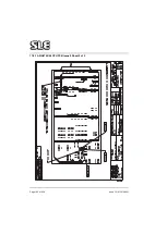
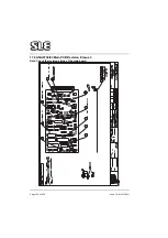
Page 99: ...Issue 10 01 10 2004 Page 99 of 258 17 5 AS A0702 04 CPU PCB Issue 5 Sheet 1 of 2 ...
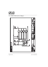
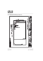
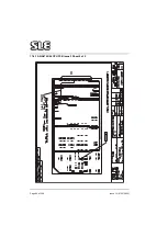
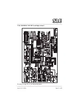
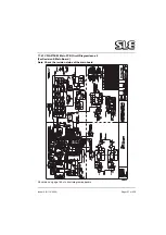
Page 100: ...Page 100 of 258 Issue 10 01 10 2004 17 5 1 AS A0702 04 CPU PCB Issue 5 Sheet 2 of 2 ...
Page 126: ...Page 126 of 258 Issue 10 01 10 2004 17 10 AS A0737 01 Bargraph Display PCB Assembly ...
Page 127: ...Issue 10 01 10 2004 Page 127 of 258 17 10 1 CD A0737 01 Bargraph Display PCB Circuit Diagram ...
Page 129: ...Issue 10 01 10 2004 Page 129 of 258 17 11 AS A0738 02 Alarm PCB Assembly ...
Page 130: ...Page 130 of 258 Issue 10 01 10 2004 17 11 1 CD A0738 02 Alarm PCB Circuit Diagram ...
Page 139: ...Issue 10 01 10 2004 Page 139 of 258 17 13 AS A0739 02 Motor Drive PCB Issue 3 Revision C ...
Page 143: ...Issue 10 01 10 2004 Page 143 of 258 17 14 AS A0756 HFO Motor Start Up PCB Issue 2 ...
Page 145: ...Issue 10 01 10 2004 Page 145 of 258 17 15 AS A0745 Pressure Drift Monitor Board Issue 1 ...
Page 147: ...Issue 10 01 10 2004 Page 147 of 258 17 16 AS A0745 Pressure Drift Monitor Board Issue 2 ...
Page 150: ...Page 150 of 258 Issue 10 01 10 2004 17 17 Serial Interface Option CD A0702 03 ...
Page 153: ...Issue 10 01 10 2004 Page 153 of 258 17 19 Front Panel ...
Page 154: ...Page 154 of 258 Issue 10 01 10 2004 17 20 SK0057 Power Supply Wiring Diagram ...
Page 156: ...Page 156 of 258 Issue 10 01 10 2004 17 22 Electronic Chassis Sheet 1 of 2 ...
Page 157: ...Issue 10 01 10 2004 Page 157 of 258 17 22 1 Electronic Chassis Sheet 2 of 2 ...
Page 186: ...Page 186 of 258 Issue 10 01 10 2004 This page is intentionally blank ...
Page 189: ...Page 189 of 258 CD A0702 04 Issue 2 ...
Page 190: ...Page 190 of 258 ...
Page 191: ...Page 191 of 258 CD A0702 04 Issue 3 ...
Page 192: ...Page 192 of 258 ...
Page 193: ...Page 193 of 258 CD A0702 04 Issue 4 ...
Page 194: ...Page 194 of 258 ...
Page 195: ...Page 195 of 258 CD A0736 03 Issue 2 Note Please check the revision status of the main board ...
Page 196: ...Page 196 of 258 ...
Page 197: ...Page 197 of 258 CD A0736 03 issue 3 Note Please check the revision status of the main board ...
Page 198: ...Page 198 of 258 ...
Page 199: ...Page 199 of 258 CD A0736 03 issue 4 Note Please check the revision status of the main board ...
Page 200: ...Page 200 of 258 ...
Page 201: ...Page 201 of 258 CD A0736 03 issue 5 Note Please check the revision status of the main board ...
Page 202: ...Page 202 of 258 ...
Page 203: ...Page 203 of 258 CD W0308 ...
Page 204: ...Page 204 of 258 ...
Page 205: ...Issue 10 01 10 2004 Page 205 of 258 Service Information and Technical Bulletins ...
Page 221: ...Issue 10 01 10 2004 Page 221 of 258 The pneumatic circuit diagram is shown here ...
Page 228: ...Page 228 of 258 Issue 10 01 10 2004 Figure 4b ...
Page 231: ...Issue 10 01 10 2004 Page 231 of 258 ...
Page 237: ...Issue 10 01 10 2004 Page 237 of 258 100nf ...
Page 258: ......

