


Issue 8 Page 89 of 286
14.0.5 Alarm Board Assembly (A0738/02)
14.0.5.1 Alarm Conditioning Circuit
The Alarm circuit comprises U1, U2 and U3. Those alarm inputs which can be muted are input
to U2 via a 4066 quad analogue switch (U1), the control pins of which are connected to the
mute timer output from the A0702/05 board PLB/7b. The non mutable alarm inputs go to U2
directly. U2 is an 8-bit comparator which outputs a logic 1 if any input differs from its reference
bit. U3 is a variable gain buffer which drives audible alarm BZ2.
14.0.5.2 O
2
Signal Processing
The pneumatic module contains a Galvanic fuel cell which monitors the oxygen concentration
delivered by the blender. The voltage output from this cell is input to U4(LT1006) and associ-
ated components, which condition the cell output voltage to the range 0-4.5V. This voltage is
then presented to the ADC U18/4 on the A0702/05 PCB and is used to display the FIO
2
.
The alarm board also contains a battery powered alarm circuit, consisting of BT1 and BZ3. The
circuit is completed when normally closed relay RL1 on the A0702/05 PCB is de-energised, as
would happen in the event of a power failure.
14.0.5.3 Power Supply Monitor
The circuit associated with the LM339N quad comparator is set up to give two comparison
‘windows’, one for the 12V rail being between 11V and 13V and the other for the 24V rail being
between 23V and 26V. If either of these rails falls outside the windows then the output transis-
tor is switched on and the buzzer is activated. The circuit requires the 5.12V supply to be pres-
ent and will continue to accurately monitor the 12V and 24V rails until the 5.12V supply drops
below the brownout level.
Summary of Contents for 2000 HFO+
Page 1: ...Issue 8 SLE 2000 HFO Ventilator Service manual High Frequency Oscillatory Ventilator ...
Page 8: ...Page 8 of 286 Issue 8 This page is intentionally blank ...
Page 9: ...Issue 8 Page 9 of 286 Introduction ...
Page 11: ...Issue 8 Page 11 of 286 Ventilator Control Description ...
Page 20: ...Page 20 of 286 Issue 8 This page is intentionally blank ...
Page 21: ...Issue 8 Page 21 of 286 Access to Internal Components ...
Page 34: ...Page 34 of 286 Issue 8 This page is intentionally blank ...
Page 35: ...Issue 8 Page 35 of 286 Maintenance ...
Page 43: ...Issue 8 Page 43 of 286 Overhual ...
Page 45: ...Issue 8 Page 45 of 286 Exchanging a Pneumatic Unit ...
Page 47: ...Issue 8 Page 47 of 286 Setup and Calibration ...
Page 74: ...Page 74 of 286 Issue 8 This page is intentionally blank ...
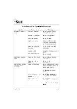
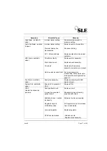
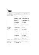
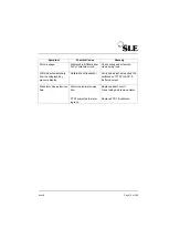
Page 75: ...Issue 8 Page 75 of 286 Troubleshooting Chart ...
Page 80: ...Page 80 of 286 Issue 8 This page is intentionally blank ...
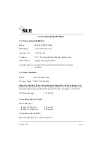
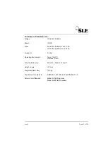
Page 81: ...Issue 8 Page 81 of 286 Technical Specification ...
Page 98: ...Page 98 of 286 Issue 8 This page is intentionally blank ...
Page 99: ...Issue 8 Page 99 of 286 Circuit Details ...
Page 100: ...Page 100 of 286 Issue 8 15 Circuit Details 15 1 A0700 03 Display Board Assembly ...
Page 101: ...Issue 8 Page 101 of 286 15 1 1 CD A0700 03 Display Board Circuit Diagram ...
Page 103: ...Issue 8 Page 103 of 286 15 2 A0701 02 LED PCB Assembly ...
Page 104: ...Page 104 of 286 Issue 8 15 2 1 CD A0701 02 LED Board Circuit Diagram ...
Page 107: ...Issue 8 Page 107 of 286 15 3 AS A0702 05 CPU PCB Issue 2 Sheet 1 of 2 ...
Page 108: ...Page 108 of 286 Issue 8 15 3 1 AS A0702 05 Issue 2 Sheet 2 of 2 ...
Page 114: ...Page 114 of 286 Issue 8 15 4 AS A0702 05 CPU PCB Issue 3 Sheet 1 of 2 ...
Page 115: ...Issue 8 Page 115 of 286 15 4 1 AS A0702 05 CPU PCB Sheet 2 of 2 ...
Page 121: ...Issue 8 Page 121 of 286 15 5 AS A0702 05 CPU PCB Issue 3 Sheet 1 of 2 See detail A ...
Page 122: ...Page 122 of 286 Issue 8 15 5 1 Ventilator CPU Board Detail A C0481 R0658 Link Cut track ...
Page 129: ...Issue 8 Page 129 of 286 15 6 AS A0736 04 Main PCB Revision E Issue 1 ...
Page 150: ...Page 150 of 286 Issue 8 15 10 AS A0739 02 Motor Drive PCB Issue 1 Sheet 1 Revision B ...
Page 151: ...Issue 8 Page 151 of 286 15 10 1 AS A0739 02 Motor Drive PCB Issue 1 Sheet 2 Revision B ...
Page 155: ...Issue 8 Page 155 of 286 15 11 AS A0739 02 Motor Drive PCB Issue 2 Revision C ...
Page 159: ...Issue 8 Page 159 of 286 15 12 AS A0756 HFO Start up Motor PCB Issue 1 ...
Page 161: ...Issue 8 Page 161 of 286 15 13 AS A0738 02 Alarm PCB Assembly ...
Page 162: ...Page 162 of 286 Issue 8 15 13 1 CD A0738 02 Alarm PCB Circuit Diagram ...
Page 165: ...Issue 8 Page 165 of 286 15 14 A0745 01 Pressure Drift Monitor Board ...
Page 166: ...Page 166 of 286 Issue 8 15 14 1 CD A0745 Pressure Drift Board Circuit Diagram ...
Page 168: ...Page 168 of 286 Issue 8 15 15 A0746 Flow Trigger PCB ...
Page 174: ...Page 174 of 286 Issue 8 15 19 Front Panel ...
Page 175: ...Issue 8 Page 175 of 286 15 20 SK0057 Power Supply Wiring Diagram ...
Page 176: ...Page 176 of 286 Issue 8 15 21 CD W0307 Electronic Pneumatic Module interconnection ...
Page 177: ...Issue 8 Page 177 of 286 15 22 Electronic Chassis S RZ 2000 HFO ...
Page 178: ...Page 178 of 286 Issue 8 ...
Page 209: ...Issue 8 Page 209 of 286 16 A3 Circuit Diagram Appendix A3 circuit Diagram Appendix ...
Page 210: ...Page 210 of 286 Issue 8 This page is intentionally blank ...
Page 211: ...Issue 8 Page 211 of 286 CD A0702 05 Issue 2 ...
Page 212: ...Page 212 of 284 ...
Page 213: ...Issue 8 Page 213 of 286 CD A0702 05 Issue 3 ...
Page 214: ...Page 214 of 284 ...
Page 215: ...Issue 8 Page 215 of 286 CD A0702 05 Issue 4 ...
Page 216: ...Page 216 of 284 ...
Page 218: ...Page 218 of 284 ...
Page 220: ...Page 220 of 284 ...
Page 222: ...Page 222 of 284 ...
Page 224: ...Page 224 of 284 ...
Page 225: ...Issue 8 Page 225 of 286 CD W0317 Issue 2 Wireloom Diagram ...
Page 226: ...Page 226 of 284 ...
Page 227: ...Issue 8 Page 227 of 286 CD W0317 Issue 3 Wireloom Diagram ...
Page 228: ...Page 228 of 284 ...
Page 229: ...Issue 8 Page 229 of 286 CD W0317 Issue 4 Wireloom Diagram ...
Page 230: ...Page 230 of 284 ...
Page 231: ...Issue 8 Page 231 of 286 Service Information and Technical Bulletins ...
Page 240: ...Page 240 of 286 Issue 8 Figure 1 Figure 2 U14 U18 U7 Solder to PCB at these points Figure 3 ...
Page 241: ...Issue 8 Page 241 of 286 Figure 4b ...
Page 247: ...Issue 8 Page 247 of 286 100nf ...
Page 262: ...Page 262 of 286 Issue 8 Pneumatic Schematic ...
Page 284: ...Page 284 of 286 Issue 8 This page is intentionally blank ...
Page 286: ......


