background image

 9

2917

14

2020

-

PJC 211 & 212

DC System - Automatic Main Switch Setup

DC System - PPC, SR150000, SR61242 Setup

MC_0097

MC_0097

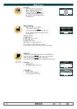
Main Switch

Location

Values: BOW/STERN/BOW-STB/STERN-STB

Set the location for selected device. Use BOW or STERN in a conventional thruster system. In a system 

with two bow or stern thrusters (i.e a catamaran), use BOW or STERN for port thruster, BOW-STB or 

STERN-STB for starboard thruster. 

(NB: If the boat has Sleipner stabilizer and AC or DC thrusters the thruster location should be set as 

BOW-STB or STERN-STB. This so the hydraulic controller are shown at the left side in display and 

thruster(s) at the right side of the display.)

PPC - DC Speed Controller PPC520/ PPC820/ PPC840/ PPC800

SR150000 - Control unit for SRV80/SRV100/SRV130/SRV170/SRV210/SRH

SR61242 - Control unit for SR80/SR100

Location

Values: BOW/STERN/BOW-STB/STERN-STB

Set the location for selected device. Use BOW or STERN in a conventional thruster system. In a system 

with two bow or stern thrusters (i.e a catamaran), use BOW or STERN for port thruster, BOW-STB or 

STERN-STB for starboard thruster. 

(NB: If the boat has Sleipner stabilizer and AC or DC thrusters the thruster location should be set as 

BOW-STB or STERN-STB. This so the hydraulic controller are shown at the left side in display and 

thruster(s) at the right side of the display.)

Direction

Values: Normal (default)/Inverted

Switches between Normal and Inverted running direction for the thruster

Function

Values: SR(V/L) ON/OFF, SRP, SRVP/SRLP, SEP, SRHP

Setup the control unit behaviour

- SR(V) ON/OFF: Retract thruster (SR6 1242 or SR150000) without speed controller (PPC520, PPC820, 

PPC800, PHC-024). 

(NB: The joystick needs to be operated more than 50% for the thruster to run.)

- SEP: Tunnel speed thruster, PPC without retract.

- SRP: Retract SR61242 with PPC, both devices needs to be set to SRP.

- SRVP/SRLP:  Retract SR150000 with PPC, both devices needs to be set to SRVP/SRLP.

- SRHP/SRAC: PHC or SAC with retract SRHP needs the PHC024 or PHC-3 hydraulic controller. 

  SRAC needs the PDC-301 SAC controller.

PPC

SR150000

SR61242

PHC 024/

PHC-3

PDC-301

SR(V/L ) ON/OFF

x

x

SRP

x

x

SRVP/SRLP

x

x

SEP

x

SRHP/SRAC

x

x

x

Max output 

Values: 50%-100%

(this is only for PPC800 from V1.022 and PPC520/820/840 from V1.008)

Set the maximum output thrust of PPC in percent.

PPC will scale the input signal to this value.

Thermo Switch

Values: Disable (default), Enable

(this is only for PPC520/820/840 from V1.016) 

Disable or Enables the thermo switch input on the PPC.

(NB: On PPC520/820/840, if the thermo switch input is closed to 0V at power-up then this function 

is automatically set to Enable.)

6.0

6.1

7.0

7.1

7.2

7.4

7.3

7.5

AC System - PDC 301 Setup

MC_0096

PDC 301

Location 

Values: BOW/STERN/BOW-STB/STERN-STB 

Set the location for selected device. Use BOW or STERN in a 

conventional thruster system. In a system with two bow or stern 

thrusters (i.e a catamaran), use BOW or STERN for port thruster, 

BOW-STB or STERN-STB for starboard thruster. 

(NB: If the boat has Sleipner stabilizer and AC or DC thrusters the thruster location should be set as 

BOW-STB or STERN-STB. This so the hydraulic controller are shown at the left side in display and 

thruster(s) at the right side of the display.)

Direction 

Values: Normal (default)/Inverted 

Switches between Normal and Inverted 

running direction for the thruster. 

Function

Values: SAC (default), SRAC

Setup the control unit behaviour.

-SAC: Tunnel speed thruster

-SRAC: SAC with SR150000 retract controller. SR150000 must be set as SRHP/SRAC.

Max output

Values: 50% to 100% (Default 100%)

Set the maximum output thrust of PHC-301 in percent.

PDC-301 will scale the input signal to this value.

Load share limit

Values: 0% to 100% (Default 100%)

The Load Sharing limitation allows the system to limit the combined load on the generator from a bow 

and stern thruster when both thrusters are used at the same time. The load sharing will dynamically 

limit the thrust request for each thruster depending on the joystick position and limit settings. 

See AC series thruster user manual (document ID 6054) for a detailed explanation and setup guide.

Summary of Contents for PJC211

Page 1: ...rikstad Norway www sleipnergroup com DOCUMENT ID REVISION DATE LANGUAGE To download your language go to www sleipnergroup com 2917 14 K e e p t h i s m a n u a l o n b o a r d 2020 EN Including Instal...

Page 2: ...up 10 Hold Calibration 11 Joystick Calibration 11 Menu System Information 11 Information PPC SR150000 SR61242 11 Information PDC101 PDC201 12 Information PDC301 12 Panel Information 12 S Link Diagnost...

Page 3: ...the same time the thruster will not run If both are operated in the same direction the thruster will run in this direction If you notice any faults with the thruster switch it off to avoid further da...

Page 4: ...ss both ON buttons simultaneously to activate control panel Information display see following pages for details Speed control joystick for bow thruster Speed control joystick for stern thruster Inform...

Page 5: ...rn thruster installation Bow and stern thruster installation Activating the bow thruster Control panel example Control panel example Control panel example Activating the stern thruster Activating both...

Page 6: ...n not be operated to auto setup is completed OR RUN SETUP DEVICES IN CONFLICT Detected devices in conflict Two or more thrusters de ned as same instance bow stern bow STB Stern STB Run Setup procedure...

Page 7: ...ERN BOW STB STERN STB BOW or STERN in a conventional thruster system In a system with two bow or stern thrusters i e a catamaran BOW and STERN is port thruster BOW STB and STERN STB is starboard thrus...

Page 8: ...tween Normal and Inverted running direction for the thruster Function Values SAC default SRAC Setup the control unit behaviour SAC Tunnel speed thruster SRAC SAC with SR150000 retract controller SR150...

Page 9: ...o the hydraulic controller are shown at the left side in display and thruster s at the right side of the display Direction Values Normal default Inverted Switches between Normal and Inverted running d...

Page 10: ...r system In a system with two bow or stern thrusters i e a catamaran use BOW or STERN for port thruster BOW STB or STERN STB for starboard thruster Thrust Values 0 100 Default 70 Set the amount of thr...

Page 11: ...devices found can ll more than one screen A scroll bar indicates the position of the selected item The joystick s operates the thrusters as normal while info is displayed This will be useful for troub...

Page 12: ...Count Receive error counter Error during reception increments the value After every successful reception the value is decremented Tx Error Count Transmit error counter Error during transmit increments...

Page 13: ...lues CELSIUS Default FAHRENHEIT Set the panel temperature displaying unit WHEN RETRACT IS OUT Values NO WARNING Default WARNING EVERY 10sec Select WARNING EVERY 10sec for external buzzer or lamp warni...

Page 14: ...t Alarm Description pages in the Auto Reset column you can see which alarms that are auto reset SPECIFIC ALARMS STOP BUTTON Pressing the STOP button on a hydraulic panel will activate the dump valve a...

Page 15: ...hown in a dual stern thruster setup Battery indicator will be shown here in a single DC electric stern thruster setup BOW STERN BOW STB STERN STB Examples of display view for different panels applicat...

Page 16: ...F to 130 C 266 F Symbol shown when a DC Thruster is used in a dual bow or dual stern setup Proportional Thruster Display Symbols MC_0053 Thrust power and direction Bow thruster s Input from bow joysti...

Page 17: ...oltage below 8 5V 15V 12V 24V system Temperature above 110 o C 230 o F None 4 Red backlight in display and continuous short beeps If one or more of the thrusters enters an alarm state Voltage below 8...

Page 18: ...anguage English Backlight Level 5 Backlight Night Colour Green Backlight Nightlevel 1 Timer Auto Off 05 min Hold Calibration 70 Bow and Stern All system devices will be erased from memory Setup proced...

Page 19: ...2 3 Motor relay fault Turn off thruster battery main switch Thruster must be serviced by authorized personnel 8 Critical Error 2 3 PPC output fail PPC must be sent for service 9 Low Motor Current 2 3...

Page 20: ...2 3 Any Stabilizer alarm See stabilizer panel for more info 28 AC Motor Overtemp Yes 1 2 3 Hydraulic AC motor power pack overtemp Higher than 120 C 248 F Stop running and wait for temperature to drop...

Page 21: ...essure parameter 0104 10503 0 16 PHC System Pressure Short Circuit System pressure sensor short circuit Wires shorted or sensor defective check wiring sensor Replace sensor 10504 0 13 PHC AI 1 Open Ci...

Page 22: ...ECI Cooling Pump Undervoltage ECI cooling pump under voltage voltage is lower than 18 0V Check PHC 3 input voltage is higher than 18 0V Replace ECI cooling pump 10524 0 55 PHC ECI Cooling Pump Overte...

Page 23: ...cient troubleshooting if necessary The installer must read this document to ensure necessary familiarity with the product before installation Instructions in this document cannot be guaranteed to com...

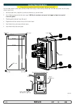
Page 24: ...cut out is jagged or chipped use a sealant to assist the gasket 3 Place the gasket to the back face of the panel 4 Plug cables into the connectors at the rear of the control panel 5 Insert the contro...

Page 25: ...Panel Height 141 5 55 141 5 55 W Panel width 83 3 3 83 3 3 a Raised height above the dashboard 65 66 2 6 65 66 2 6 b Depth behind the dashboard not inc cables 31 8 1 25 31 8 1 25 c Panel screw hole d...

Page 26: ...imum Units Comment Input voltage 9 31 Volt DC Powered from S Link Current Voltage 20 120 mA External Alarm Buzzer Voltage 31 Volt DC External Alarm Buzzer Current 500 mA Internally fused Technical Spe...

Page 27: ...shall be connected to GND and the red wire connected to 12VDC or 24VDC To reduce the risk of interference avoid routing the S Link cables close to equipment such as radio transmitters antennas or high...

Page 28: ...black red B B 05M 05M 5A 12 24 5A 12 24 PPC PJC 212 Proportional joystick control panel Bow and stern Station 1 S PJC 212 Observe PPC battery terminal polarity S S 12 24V 5A S link on off switch red...

Page 29: ...Serial number ie Thruster AMS PPC etc Bow Bow STB Stern Stern STB Fill in the type location and serial numbers of the S link devices installed Keeping this as a reference will make the setup procedur...

Page 30: ...ned to the Purchaser at the Warrantor s expense If on the other hand the claim is determined to result from circumstances such as described in section 4 above or a result of wear and tear exceeding th...

Page 31: ...31 2917 14 2020 PJC 211 212 MC_0037 Notes...

Page 32: ...accuracies or omissions it may contain Continuous product improvement may change the product speci cations without notice Therefore Sleipner Motor AS can not accept liability for any possible differen...

Reviews: