3
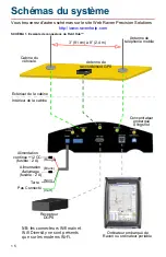
3. Place the cellular antenna bases on a suitable magnetic surface for
mounting. Review the
Best Installation Practices
on page 2 and refer to
the alternative mounting methods if a suitable magnetic location is not
available on the vehicle or implement.
4. Connect the cable from the cellular antenna bases to the ‘Antenna/Cellular
Main’ and ‘Diversity/Cellular Diversity’ ports on the back of the Field Hub.
5. Place the GPS patch antenna on the highest suitable magnetic surface on
the vehicle or implement. Review the
Best Installation Practices
on
page 2 and refer to the alternative mounting methods if a suitable magnetic
location is not available.
6. Route the patch antenna cable to the port labeled ‘GPS’ on the back of the
Field Hub.
7.
Wi-Fi Field Hub Option Only
- Connect the Wi-Fi antennas to the ‘WiFi
Main’ and ‘WiFi Diversity’ ports on the back of the Field Hub.
8. Connect the lead wires on the supplied Field Hub power cable:
Warning:
To prevent damage to the Field Hub, do not connect the 4-pin
power connector to the Field Hub until the power and ground
leads are installed per the following instructions.
Do not connect the red lead wire directly to the machine
battery.
• Connect the black lead to a clean ground (i.e. vehicle junction box).
• Connect the red lead to a clean, co12 V DC power source
(i.e. unswitched at a junction box).
• Connect the white lead to the vehicle ignition switch.
• Cut or cover the green lead wire. This lead is not used.
Note:
If the power cable is installed as described above, the vehicle ignition
switch will control the Field Hub power-up and shutdown. When the
ignition switch is turned off, the Field Hub will perform a shutdown
sequence before powering off completely.
9. Route the 4-pin connector on the supplied power cable into the vehicle cab
and connect to the ‘Power’ plug on the back of the Field Hub.
Warning:
Do not route through possible crimp points such as vehicle
windows or doors.
10.Connect the appropriate Raven serial cable to the ‘RS-232’ port on the
back of the Field Hub and route the cable to the input port on your GPS
receiver. Contact your GPS receiver manufacturer for any necessary
adapter cables or more information.
Warning:
Use only Raven approved serial cables designed specifically
for your GPS receiver or data overages may result. Contact
your local Slingshot™ dealer for appropriate cable part
number and ordering information.
11.Connect the supplied ethernet cable to the ‘Ethernet’ port on the back of
the Field Hub and route to a web compatible device such as a Raven field
computer.
Summary of Contents for Field Hub
Page 1: ...Guia de Instala o Installation Guide Guide d installation Field Hub Manual de instalaci n TM...
Page 4: ...2 Sling shot RTK 36 Wi Fi 36 36 37 38...
Page 5: ...3...
Page 36: ...3 1...
Page 44: ...3 9...
Page 46: ......


