4.
Center the tail wheel bracket on the rear of the fuselage and screw in place using
three of the supplied wood screws. Remove the screws and harden the holes with
a drop of thin CA. Allow the CA to cure and then permanently install the tail wheel
bracket.
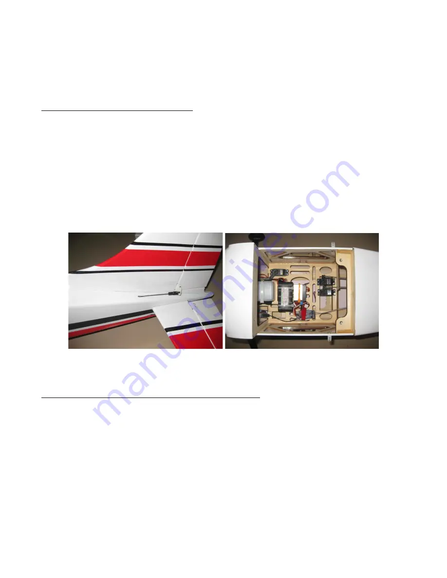
RUDDER CONTROL INSTALLATION:
1. The ARF is supplied with a pushrod for the rudder. Guide the rod through the
plastic sleeve in the fuselage. Make sure that the threaded end is on the rudder
side. Install the plastic control horn supplied on the rudder. Make sure that you
place the horn in line with the pushrod. Install the clevis onto the rod and clip it to
the horn.
2.
Install your rudder servo into the pre-cut location in the fuselage. You will need a
0.75 inch arms on the servo. Set up your radio accordingly and center the rudder
servo. The geometry of your servo arm relative to the rudder horn is critical for
proper rudder operation without binding.
ENGINE EXHAUST
&
FUEL SYSTEM INSTALLATION:
1. Use the provided template that comes with your engine (if provided) to align the
engine. The center line for the mounting of the engine is marked on the firewall.
2.
Use the guide to align the engine and drill the mounting holes. You may have to
cut the firewall as necessary if using a rear-carburetor engine. Notice that the
engine center line is offset to the 1eft to compensate for the right thrust built into
the engine box.
.
3.
Place the cowling in place on the fuselage and measure the distance from the
firewall to about 0.5 inch in front of the cowling. This figure represents the back of
the spinner and will help you determine if you need to space your engine out from
the firewall using washers or additional wood. Mount your engine securely using


