background image

1.

  Magnetic base not holding securely


Material is too thin to engage magnet.


Surface of material being drilled must be free of chips, debris, rust and mill scale.


Size of cutter exceed machine’s rated capacity.


Check magnet face for unevenness, nicks and burrs.


Welding equipment connected to material being drilled.


Dull cutter.

2.

  Drill motor running, arbor and spindle not turning


Possible sheared spindle key.


3.

  Motor slows when drilling


Refer to page 6 for recommended wire gages and cord lengths. 


Excessive downfeed pressure during drilling cycle will cause motor to slow and overheat.


Cutting tool needs to be resharpened.

4. 

 Coolant system not working


Coolant system is gravity dependent. Machine must be in a upright position to operate properly.


Check operation of coolant valve. Valve must turn freely.


Check coolant lines for blockage. 


Dirt or debris in coolant tank.


Consistency of coolant mixture too thick.


Incorrect pilot pin being used.


Vent hole in coolant tank lid blocked.


Lid on too tight.


Bottle pressurized.

5. 

 Slugs not ejecting from cutter


Lack of coolant causing slugs to expand in cutter bore.


Incorrect pilot pin being used.


Possible broken internal arbor parts.

6.

  Breaking cutters


Coolant must be supplied to interior of cutter.


Excessive feed pressure being applied when cutter initially contacts work surface.


Confirm material hardness.


Drilling stacked materials with incorrect cutter.


Dull cutters; dull or chipped cutting edges require excessive feed pressure, resulting in breakage.


Excessive arbor runout – see regular maintenance on page 10.


Improperly adjusted motor slide – see page 10.

7.

  Oversized or rough holes


Insufficient coolant.


Excessive feed pressure.


Dull cutter.


Motor slide improperly adjusted.

basic


troubleshooting

9

Summary of Contents for 17985

Page 1: ...TECTION REQUIRED MODEL 17985 120V OR 17987 220V Serial Date of Purchase WARNING before use be sure everyone using this machine reads and understands all safety and operating instructions in this manua...

Page 2: ...y Jancy Engineering Inc will within one 1 year from the original date of purchase repair or replace any goods found to be defective in materials or workmanship provided the product warranty registrati...

Page 3: ...not expose power tools to rain or wet conditions Water entering a power tool will increase the risk of electric shock d Do not abuse the cord Never use the cord for carrying pulling or unplugging the...

Page 4: ...t of the reach of children and do not allow persons unfamiliar with the power tool or these instructions to operate power tool Power tools are dangerous in the hands of untrained users e Maintain powe...

Page 5: ...ar cutting area or rotating machine parts 6 Always use eye and hearing protection 7 Always use safety strap and chip guard provided with machine 8 Always use proper tooling Keep cutters securely faste...

Page 6: ...contacting power source tie a drip loop in power cord as shown in Figure B Use only 3 wire extension cords that have 3 prong grounding type plugs and 3 pole receptacles that accept the tool s plug Rep...

Page 7: ...NOTE Feed hub assembly is mounted on right side of machine frame if necessary it can be reversed for lefthand operation by simply removing the fastener item 24 and hub item 21 from frame Remove hub p...

Page 8: ...erials may require an additional steel backing plate to achieve proper magnet adhesion 2 Start drill motor by depressing green motor ON button 3 Using the feed handles advance cutter into material unt...

Page 9: ...ant valve Valve must turn freely Check coolant lines for blockage Dirt or debris in coolant tank Consistency of coolant mixture too thick Incorrect pilot pin being used Vent hole in coolant tank lid b...

Page 10: ...olant system reservoir o rings lip seals and coolant collar for wear 7 Inspect motor brushes and replace as needed 8 Replace any worn parts and regularly tighten fasteners that have become loose durin...

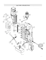
Page 11: ...machine breakdown 11 Rev D...

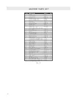
Page 12: ...1 17 M8 X 30 SHCS UH0814 2 18 M8 LOCK WASHER UH2082 4 19 M8 X 25 SHCS UH0812 2 20 CONTROL PANEL ASSEMBLY 120V 07310P 1 CONTROL PANEL ASSEMBLY 220V 07312P 21 PINION HUB 07320 1 22 SPOKE HANDLE 07319 3...

Page 13: ...LOCKING PCB SUPPORT 054133 1 4 7 CIRCUIT BOARD 054127 1 8 ENCLOSURE 054126 1 9 M4 X 10 CRPHMS UH0420 4 10 M4 LOCK WASHER UH2044 4 11 LABEL PANEL PLATE 07379 1 12 WIRE GROUP 2 NOT SHOWN 07380 1 13 WIRE...

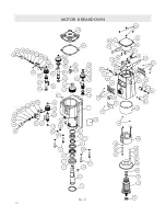
Page 14: ...motor breakdown Rev D 14...

Page 15: ...45 SNAP BUSHING 07441 3 ITEM DESCRIPTION PART QTY 46 SPECIAL WASHER 07443 1 47 M5 X 12 DOWEL PIN UH4200 1 48 GEARBOX GASKET 04593 1 49 GEAR CASE COVER 07442 1 50 M8 LOCK WASHER UH2083 4 51 M8 X 40 SHC...

Page 16: ...ng Inc 01 11 other available Slugger drills description model max diameter depth capacity USA5 120V 18066 2 3 8 3 USA5 220V 18080 2 3 8 3 USA101 120V USA101 1 1 2 2 USA101 220V USA101 2 1 1 2 2 USA200...

Reviews: