background image

14

en

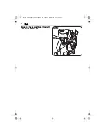
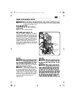
Mounting the coolant hose (figure 7).

Connect the coolant hose.

OBJ_BUCH-0000000130-002.book  Page 14  Monday, November 18, 2013  10:38 AM

Summary of Contents for JCM 200 AUTO

Page 1: ...Inc 1030 Alcon Street Pittsburgh PA 15220 Telephone 412 922 8886 Toll Free 1 800 441 9878 www feinus com Headquarter C E FEIN GmbH Hans Fein Stra e 81 D 73529 Schw bisch Gm nd Bargau www fein com JCM...

Page 2: ...2 Instruction Manual Instrucciones de uso en 3 es 26 OBJ_BUCH 0000000130 002 book Page 2 Monday November 18 2013 10 38 AM...

Page 3: ...electric shock b Avoid body contact with earthed or grounded surfaces such as pipes radia tors ranges and refrigerators There is an increased risk of electric shock if your body is earthed or grounded...

Page 4: ...sories and tool bits etc in accordance with these instructions taking into account the working conditions and the work to be performed Use of the power tool for operations different from those intende...

Page 5: ...nding sanding polishing sawing or for other work procedures where material is removed dusts develop that are both hazardous to one s health and can spontaneously combust or be explosive Contact with o...

Page 6: ...work place LpA re 20 Pa in decibels 82 4 82 4 82 4 82 4 Measuring uncertainty KpA in deci bels 3 3 3 3 Measured A weighted sound power level LwA re 1 pW in decibels 93 4 93 4 93 4 93 4 Measuring uncer...

Page 7: ...closed documents such as the Instruction Man ual and the General Safety Instructions Observe the instructions in the text or graphic opposite Observe the instructions in the text or graphic opposite B...

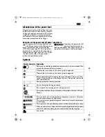
Page 8: ...manual machine operation Symbol character Explanation Character Unit of measurement national Explanation n0 rpm min min 1 r min No load speed P W Electrical power Angle width U V Electric voltage f Hz...

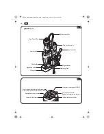
Page 9: ...ng of the power tool All accessories described or shown in this instruction manual will not be included with your power tool WARNING Application tool Tool holder Viseo Touch Pad Drill motor cable Cool...

Page 10: ...h Chip guard Spoke handle Tool holder Switches the magnet On Off Starts the drill motor Rotation direction clockwise Speed reduction in steps Starts the drill motor in inch mode Rotation direction ant...

Page 11: ...apacity in steel high speed steel HSS core drill bit 7 16 in 1 5 8 in 12 mm 40 mm 7 16 in 1 5 8 in 12 mm 40 mm 7 16 in 1 5 8 in 12 mm 40 mm 7 16 in 1 3 16 in 12 mm 45 mm Drilling capacity in steel hig...

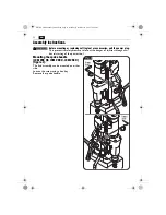
Page 12: ...ure rules out the danger of injuries through acci dental starting of the power tool Mounting the spoke handle JCM 200 QX JCM 200 U JCM 256 U figure 4 The hub assembly can be mounted on either side Loo...

Page 13: ...olant container Fill in pump feedable cooling lubricant e g Slugger cutting oil Screw the cap onto the coolant container again Filling the dismounted coolant container figure 6 Pull the empty coolant...

Page 14: ...14 en Mounting the coolant hose figure 7 Connect the coolant hose OBJ_BUCH 0000000130 002 book Page 14 Monday November 18 2013 10 38 AM...

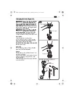
Page 15: ...r Pull the clamping sleeve of the tool holder down and insert the core drill bit with the centering pin into the tool holder Do not touch the sharp edges of the core drill bit Danger of injury Drill c...

Page 16: ...tly the magnetic holding power is sufficient and the power tool can be operated with man ual or automatic feed When the Magnet button on the control panel flashes green the magnetic holding power poss...

Page 17: ...tening levers with the other hand Adjust the desired stroke range Tighten both fastening levers again Adjusting the working position JCM 256 U figure 12 Release the fine adjustment clamping lever Adju...

Page 18: ...valve to the position shown For switching off or when working overhead deactivate the cooling lubri cant flow Shut the ventilation and turn the flow valve to the position shown When working overhead...

Page 19: ...t Drilling capacity in steel high speed steel HSS twist drill bit Tapped hole JCM 200 U JCM 200 QX JCM 200 auto 1 Gear 27 50 mm 1 1 16 in 2 in 21 40 mm 3 16 in 1 5 8 in 16 mm 23 mm 5 8 in 7 8 in M6 M1...

Page 20: ...m bol To stop the drill motor press the symbol Do not stop the drill motor during the drilling procedure To start the drill motor with counterclock wise rotation press the button with the symbol The d...

Page 21: ...rough detection Upon completion of the drilling procedure the power tool detects the break through and the drill motor automati cally returns to the starting position The drill motor does not switch o...

Page 22: ...ide tipped cutter should remain stuck in the material stop the drill motor and carefully turn the carbide tipped cutter out clockwise After each drilling operation remove the chips and the slug Do not...

Page 23: ...vice carried out only through an authorized Slugger repair facility When replacing the power tool s protective cable bushing or cord between the drill stand and drill motor is required this must be ca...

Page 24: ...oling lubricant system Flush the cooling lubricant system with water clean and drain it completely when not using the machine for periods longer than two weeks Warranty and liability The warranty for...

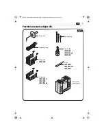
Page 25: ...ase JCM 256 U JCM 200 QX JCM 200 U JCM 200 auto JCM 200 U JCM 200 auto JCM 256 U JCM 200 U JCM 200 auto JCM 256 U Fig 20 Chip hook Clamping strap Chip guard Chip guard Centering pin Tool holder OBJ_BU...

Page 26: ...explosi n en el que se encuentren combustibles l qui dos gases o material en polvo Las herramientas el ctricas producen chis pas que pueden llegar a inflamar los materiales en polvo o vapores c Mante...

Page 27: ...o de estos equipos reduce los riesgos deriva dos del polvo 4 Trato y uso cuidadoso de herramientas el ctricas a No sobrecargue el aparato Use la herra mienta prevista para el trabajo a reali zar Con l...

Page 28: ...de protecci n sometidas a una ins pecci n peri dica Un cable de protecci n defectuoso puede provocar una descarga el ctrica Para no lesionarse siempre mantenga las manos ropa etc alejadas de las viru...

Page 29: ...bajo El riesgo derivado de la inspiraci n de mate rial en polvo depende de la frecuencia con la que se trabajen estos materiales Los materia les que contengan amianto solamente debe r n ser procesados...

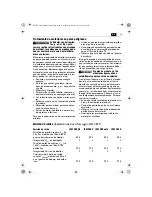
Page 30: ...e sufi ciente potencia y cumplan los requisitos seg n norma ISO 8528 para la clase de ejecu ci n G2 Deber prestarse especial atenci n a no sobrepasar el coeficiente de distorsi n m ximo del 10 estable...

Page 31: ...sobre una situaci n peligrosa inminente Un com portamiento incorrecto puede dar lugar a una lesi n grave o incluso mor tal Este s mbolo advierte sobre una situaci n peligrosa que puede comportar lesio...

Page 32: ...V Unidad de medida de la tensi n el ctrica f Hz Unidad de medida de la frecuencia I A Unidad de medida de la intensidad m lbs Unidad de medida de la masa l ft in Unidad de medida para la longitud anch...

Page 33: ...l de serie suministrado con su herramienta el ctrica puede que no corresponda en su totalidad al material descrito o mostrado en estas instrucciones de servicio ADVERTENCIA til Viseo Touch Pad L nea d...

Page 34: ...rda contra virutas Conexi n y desconexi n el im n Arranque del motor de taladrar Sentido de giro a derechas Reducci n escalonada de la velocidad Arranque del motor de taladrar con pulsador Sentido de...

Page 35: ...5 8 in 12 mm 65 mm Di metro de taladro en acero metal duro corona perforadora 7 16 in 1 5 8 in 12 mm 40 mm 7 16 in 1 5 8 in 12 mm 40 mm 7 16 in 1 5 8 in 12 mm 40 mm 7 16 in 1 3 16 in 12 mm 45 mm Di m...

Page 36: ...evita los accidentes que pudieran presentarse en caso de una puesta en marcha involuntaria Montaje de la palanca JCM 200 QX JCM 200 U JCM 256 U Figura 4 Es posible acoplar la palanca al lado que Ud pr...

Page 37: ...efrigerante apro piado para ser bombeado p ej aceite de corte Slugger Vuelva a cerrar el tap n del dep sito de refri gerante Llenado del dep sito de refrigerante desmon tado Figura 6 Saque el dep sito...

Page 38: ...38 es Montaje de la manguera de refrige rante Figura 7 Conecte la manguera de refrigerante OBJ_BUCH 0000000130 002 book Page 38 Monday November 18 2013 10 38 AM...

Page 39: ...l perno de centrado por la corona per foradora Jale hacia abajo el casquillo tensor del porta tiles y aloje en el mismo la corona perfora dora junto con el perno de centrado No toque los filos cortant...

Page 40: ...a fuerza de sujeci n magn tica para poder trabajar con la herramienta el ctrica tanto con avance manual como con avance autom tico Si la tecla verde Magnet del panel de mando parpadea es probable que...

Page 41: ...palancas de sujeci n con la otra mano Ajuste el recorrido deseado Vuelva a apretar ambas palancas de sujeci n Ajuste de la posici n de trabajo JCM 256 U Figura 12 Afloje la palanca de bloqueo del ajus...

Page 42: ...da Al desconectar el aparato o realizar trabajos por encima de la cabeza corte el paso de refrigerante Cierre el pur gador y gire la llave de paso a la posi ci n mostrada Al realizar trabajos por enci...

Page 43: ...perforadora Di metro de taladro en acero acero de corte de alto rendimiento broca helicoidal Taladro para roscar JCM 200 U JCM 200 QX JCM 200 auto 1 veloci dad 27 50 mm 1 1 16 in 2 in 21 40 mm 3 16 in...

Page 44: ...e la tecla Para detener el motor de taladrar pulse la tecla No detenga el motor de taladrar durante la perforaci n Para arrancar el motor de taladrar con giro a izquierdas pulse la tecla con el s mbol...

Page 45: ...sa la broca el material Al concluirse el proceso de taladrado la herramienta el ctrica detecta cuando es traspasado el material y el motor de taladrar retorna autom ticamente a la posici n inicial El...

Page 46: ...el motor de taladrar y vaya sacando la corona perforadora gir ndola con cuidado en sentido contrario a las agujas del reloj Al terminar de taladrar retire las virutas y el n cleo resultante de la per...

Page 47: ...ugger En caso de que se da e la l nea de la herramienta el ctrica es necesario sustituirla por una l nea de refacci n original adquirible a trav s de uno de los ser vicios t cnicos Slugger La lista de...

Page 48: ...e refrigeraci n Enjuague el circuito de refrigeraci n con agua l mpielo y vac elo completamente si tiene previsto no utilizar la m quina durante m s de dos semanas Garant a La garant a del producto se...

Page 49: ...orte JCM 256 U JCM 200 QX JCM 200 U JCM 200 auto JCM 200 U JCM 200 auto JCM 256 U JCM 200 U JCM 200 auto JCM 256 U Fig 20 Cinta tensora Cinta tensora Guarda contra virutas Guarda contra virutas Perno...

Reviews: