background image

6

en

– Materials for pesticide treatment on boat 

and ship hulls.

To minimize the unwanted intake of these 
materials:
– Use dust extraction matched appropriately 

for the developing dust.

– Use personal protective equipment, such as 

a P2 filter-class dust protection mask.

– Provide for good ventilation of the work-

place.

The risk from inhaling dusts depends on the 
frequency how often these materials are 
worked. Materials containing asbestos may 
only be worked by specialists.

Wood and light-metal dust can 
cause spontaneous combustion 
or explosions.

Hot mixtures of sanding dust and paint/var-
nish residuals or other chemical materials in 
the filter bag or the vac filter can self-ignite 
under unfavourable conditions, such as spark-
ing from sanding metal, continuous sunlight 
or high ambient temperatures. To prevent 
this:
– Avoid overheating the material being 

sanded and the power tool.

– Empty the dust collector/container in time.
– Observe the material manufacturer’s work-

ing instructions.

Observe the relevant regulations for the 
materials being worked.

Emission values for sound

 (Two-figure – specifications as per ISO 4871)

CAUTION

Sound emission

JCM312U

JCM312auto

A-weighted emission pressure power level 
measured at the workplace L

pA

 (re 20 µPa), in 

decibels

84

84

Measuring uncertainty K

pA

, in decibels

3

3

Measured A-weighted sound power level L

wA


(re 1 pW), in decibels

95

95

Measuring uncertainty K

wA

, in decibels

3

3

Measured C-weighted peak sound pressure 
level L

pCpeak

, in decibels

101

101

Measuring uncertainty K

pCpeak

, in decibels

3

3

REMARK: The sum of the measured emission value and respective measuring inaccuracy rep-
resents the upper limit of the values that can occur during measuring.

Wear ear protection!

Measured values determined in accordance with the corresponding product standard.

3 41 01 169 21 0.book  Seite 6  Mittwoch, 7. September 2011  3:32 15

Summary of Contents for JCM312auto

Page 1: ...C E FEIN GmbH Printed in Germany Figure not obligatory Subject to technical changes 3 41 01 169 21 0 BY 2011 09 bH 81 isch Gm nd Bargau JCM312U 7 270 38 JCM312auto 7 270 39 011 3 02 15...

Page 2: ...2 English _____________ Instruction manual___________________ Espa ol _____________ Instrucciones de uso _________________ 3 25 3 41 01 169 21 0 book Seite 2 Mittwoch 7 September 2011 3 32 15...

Page 3: ...u to lose control 2 Electrical safety a Power tool plugs must match the outlet Never modify the plug in any way Do not use any adapter plugs with earthed grounded power tools Unmodified plugs and matc...

Page 4: ...connect the plug from the power source and or the battery pack from the power tool before making any adjustments changing accessories or storing power tools Such preventive safety measures reduce the...

Page 5: ...t rivet or screw any name plates or signs onto the power tool If the insulation is dama ged protection against an electric shock will be ineffective Adhesive labels are recommen ded Do not use accesso...

Page 6: ...ting the material being sanded and the power tool Empty the dust collector container in time Observe the material manufacturer s work ing instructions Observe the relevant regulations for the material...

Page 7: ...ling with annular tools and twist drill bits reaming countersin king and tapping on materials with surfaces suitable for magnets in weather protected environments using the cutting tools and accessori...

Page 8: ...ction during operation This symbol confirms the certification of this product for the USA and Canada This sign warns of a directly imminent dangerous situation A false reac tion can cause a severe or...

Page 9: ...Frequency f V Electric voltage I A Electric current intensity Angle width m lbs Mass l ft in Length height depth diameter and tapping m s kg A mm V W Hz N C dB rpm m s2 Basic and derived units of meas...

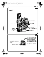
Page 10: ...dental starting of the power tool All accessories described or shown in this instruction manual will not be included with your power tool WARNING Fig 1 JCM312auto Coolant container Spoke handle with f...

Page 11: ...N Max tool holder Gear switch Cutting tool Button for cooling lubricant supply Button for speed reduction Stop motor button Button for starting the drill motor in clockwise direction Button for starti...

Page 12: ...lass of protection I I Core drilling capacity in steel TCT carbide tipped cutter 12 80 mm 7 16 in 3 1 8 in 12 80 mm 7 16 in 3 1 8 in Core drilling capacity in steel HSS high speed steel 12 65 mm 7 16...

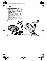
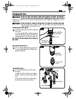
Page 13: ...lead to electric shock Tie a bow in the cord near the plug so that any liquid can drip off Only use water soluble cutting fluid that is capable of being pumped like Slugger Cutting Fluid Filling the...

Page 14: ...the coolant tank Fill in pump feedable water soluble Slugger Cutting Fluid Do not use oil Firmly screw the bottom closing cap back on to the coolant tank Insert the filled coolant tank into the holder...

Page 15: ...r Pull the QuickIN Max clamping sleeve of the tool holder downward Insert the carbide tipped cutter with the pilot pin Do not touch the sharp edges of the carbide tip ped cutter Key type drill chuck F...

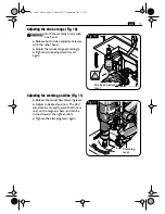
Page 16: ...is suffi cient and the machine can be operated with automatic feed When the red warning light in the button of the control panel and the main switch flash the magnetic holding power is insufficient an...

Page 17: ...evers again Adjusting the working position Fig 11 Release the swivel base clamping lever Adjust to desired position The drill stand can be moved toward the front or rear on the magnetic base and can b...

Page 18: ...st the gear setting only when the machine is at a complete stop Set the switch to gear 1 to work at low speed with high torque This setting is suitable for drilling with large cutting tools large dril...

Page 19: ...d press the button To stop the drill motor press the button Do not stop the drill motor during the drilling procedure To start the motor with anticlockwise rotation press the button with the symbol Th...

Page 20: ...ed and the drill motor moves back to the starting position Do not rotate the spoke handle during automatic feed operation Do not use the automatic feed when tapping Manual feed JCM312auto Fig 14 Posit...

Page 21: ...g If the carbide tipped cutter should remain stuck in the material stop the drill motor and carefully turn the carbide tipped cutter out clockwise Remove the chips and the slug after each dril ling pr...

Page 22: ...s For continuous operation the cooling lubri cant system must be flushed with water and cleaned approx every 4 weeks Exchangeable parts If required you can change the following parts yourself Applicat...

Page 23: ...o clean clogged or dirty ventilation openings of the power tool with pointed metal objects use non metal tools or objects if necessary Do not use cleaning agents and solvents that can cause damage to...

Page 24: ...ing case QuickIN tool holder Key type drill chuck 1 16 in 1 2 in with chuck key an QuickIN adapter Chip hook Drift Quick IN Max tool holder Pilot pin Safety strap Chip guard 3 41 01 169 21 0 book Seit...

Page 25: ...identes b No utilice la herramienta el ctrica en un en torno con peligro de explosi n en el que se en cuentren combustibles l quidos gases o mate rial en polvo Las herramientas el ctricas pro ducen ch...

Page 26: ...y el pelo largo se pueden enganchar con las piezas en movimiento g Siempre que sea posible utilizar unos equi pos de aspiraci n o captaci n de polvo aseg rese de que stos est n apropiada mente conecta...

Page 27: ...les de conexi n en perfectas condiciones y unas extensiones provistas de un contacto de protecci n sometidas a una inspecci n peri dica Un cable de protecci n defectuoso puede provocar una descarga el...

Page 28: ...ice un equipo de aspiraci n apropiado para el polvo producido Use equipos de protecci n personal como por ejemplo una mascarilla contra polvo con un filtro de la clase P2 Observe que est bien ventilad...

Page 29: ...trica a grupos electr genos de alterna de potencia suficiente y que no distorsionen la curva de tensi n Esta prohibido conectar la herramienta el ctrica a gene radores de corriente cuya tensi n en vac...

Page 30: ...e este producto ha sido certificado en USA y Canad Este s mbolo advierte sobre una situaci n peligrosa inminente Un com portamiento incorrecto puede dar lugar a una lesi n grave o incluso mor tal Este...

Page 31: ...n el ctrica f V Frecuencia I A Intensidad Angulo m lbs Masa l ft in Longitud ancho altura profundidad o di metro m s kg A mm V W Hz N C dB rpm m s2 Unidades b sicas y unidades derivadas del sistema in...

Page 32: ...nvoluntaria Todos los accesorios descritos o mostrados en estas instrucciones de uso no se incluyen con la herramienta el ctrica suministrada ADVERTENCIA Fig 1 JCM312auto Dep sito de refrigerante Pala...

Page 33: ...o tensor QuickIN Max Selector de velocidad til Tecla para paso de refrigerante Tecla para reducci n de las revoluciones Tecla para detenci n del motor Tecla de arranque del motor de taladrar con giro...

Page 34: ...tecci n I I Di metro de taladro en acero TCT cortador con inserto de tungsteno 12 80 mm 7 16 in 3 1 8 in 12 80 mm 7 16 in 3 1 8 in Di metro de taladro en acero HSS acero de corte r pido de alto rendim...

Page 35: ...ntes del enchufe para permitir que el l quido gotee del cable Como refrigerante deber emplearse un medio de refrigeraci n apto para ser bombeado como p ej Slugger Cutting Fluid Llenado del dep sito de...

Page 36: ...quido refrigerante Slugger Cut ting Fluid soluble en agua apropiado para ser transportado por la bomba No utilizar aceite Vuelva a enroscar firmemente el tap n inferior del dep sito de refrigerante C...

Page 37: ...pudieran pre sentarse en caso de una puesta en marcha involuntaria Cortador con inserto de tungsteno Figura 6 Inserte el perno piloto en el cortador con inserto de tungsteno Jale hacia abajo el casqui...

Page 38: ...leteado hasta que gire loco Saque el porta tiles con la cu a extractora Limpie el cono interior del eje motriz y monte la broca 1 2 3 4 Fig 8 Broca Cu a extractora Anillo moleteado 3 41 01 169 21 0 bo...

Page 39: ...n tica de sujeci n y la m quina puede trabajar con avance autom tico Si el piloto rojo parpadea en la tecla del panel de mando y en el conmutador del im n del soporte de taladrar puede que no sea sufi...

Page 40: ...ido Ajuste de la posici n de trabajo Figura 11 Afloje la palanca de bloqueo de la base giratoria Ajuste la posici n deseada El soporte de taladrar puede desplazarse sobre la base magn tica hacia delan...

Page 41: ...e Solamente accione el selector de velocidades con el motor completamente detenido Seleccione la 1 a velocidad para traba jar a bajas revoluciones con un torque elevado Este ajuste es apropiado para r...

Page 42: ...con el s mbolo Para detener el motor de taladrar pulse la tecla con el s mbolo No detenga el motor de taladrar mien tras est taladrando Para arrancar el motor con giro a izquierdas pulse la tecla con...

Page 43: ...el motor de taladrar es regresado a la posici n de partida Durante el avance autom tico no gire manualmente la palanca No utilice el avance autom tico para roscar Avance manual JCM312auto Figura 14 C...

Page 44: ...steno llega a atascarse en el material detenga el motor de taladrar y vaya sacando el cortador gir ndolo con cuidado en el sentido de las agujas del reloj Al terminar de taladrar retire las virutas y...

Page 45: ...m s de dos semanas Tambi n en el caso de un uso frecuente es necesario enjuagar y limpiar el circuito de refrigeraci n cada 4 semanas aprox Piezas sustituibles Si fuese preciso puede sustituir Ud mism...

Page 46: ...adicional No intente limpiar las rejillas de refriger aci n de la herramienta el ctrica con objetos met licos en punta emplee para ello objetos que no sean de metal No aplique agentes de limpieza ni...

Page 47: ...nsporte QuickIN Portabrocas de corona dentada 1 16 1 2 con llave y adaptador QuickIN Gancho para virutas Cu a extractora Quick IN Max Perno piloto Correa de seguridad Guarda contra virutas 3 41 01 169...

Reviews: