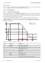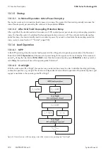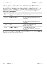
Position
Parameter
Description
4
‒
Grid limit level 1 is breached, timer for B starts counting
5
‒
Grid limit level 2 is breached, timer for A starts counting
6
‒
Grid limit level 2 is breached for delay time level 2 → grid disconnec-
tion
7
‒
Grid limit level 1 is breached for delay time level 1 → grid disconnec-
tion (has already occurred on level 2)
8
‒
Connection conditions fulfilled → grid monitoring time starts counting
9
‒
Utility grid within valid range during grid monitoring time → grid con-
nection
13.1.3.2 Monitoring the Power Frequency
In the operating state "Grid monitoring",
Waiting for valid AC grid
appears on the touch display. The grid limits are
monitored continuously from now on. If no grid error occurs during the grid monitoring time, the AC contactor closes
and the inverter switches to the operating state "Grid monitoring time reached". If the grid limits are exceeded during
the monitoring time, the inverter will restart "Grid monitoring".
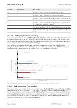
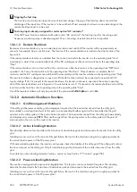
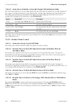
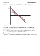
You can specify the thresholds and delay times manually. For frequency monitoring, three thresholds can be
configured for both overfrequency and underfrequency. For example, at an overfrequency of 50.5 Hz, tripping can
take place after one second, and at an overfrequency of 51.5 Hz already after 0.1 seconds.
Figure 60: Tripping characteristics and time behavior as exemplified by frequency monitoring with the set parameters
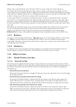
13.1.4 Grid Monitoring Time Reached
The inverter is in the operating state "Grid monitoring time reached".
Waiting for PV voltage
or
Waiting for utilities
company
appears on the touch display. If the input voltage V
PV
exceeds the start voltage
PvVtgStrLevMin
, the
inverter waits until the time specified in parameter
PvStrT
has elapsed. If the input voltage V
PV
does not fall below the
start voltage
PvVtgStrLevMin
during this time, the inverter checks whether the utility grid is connected. If a valid AC
grid is connected, the inverter switches to the operating state "Startup". The start voltage
PvVtgStrLevMin
must be
adjusted to conform with the PV array connected to the inverter.
13 Function Description
SMA Solar Technology AG
System Manual
181
MVPS22JP-SH-en-11
Summary of Contents for 1000-1SC
Page 257: ......

