If the Remote GFDI trips, initially a temporary error will be assumed and a motor drive will close the Remote GFDI after
a defined waiting time. No external switch command is required to close the tripped Remote GFDI. The inverter can
switch back to feed-in operation after a waiting time. In the default setting of the inverter, the software will attempt to
start the Remote GFDI up to three times per day. If the Remote GFDI is tripped on several consecutive days, the
software assumes a permanent insulation error and the inverter will no longer switch back on. In this case, a qualified
person will need to check and, if necessary, repair the insulation and then acknowledge the error.
13.2.3.4 Insulation Monitoring Device
Depending on the order option, an insulation monitoring device can monitor the insulation resistance of the PV power
plant in ungrounded PV arrays.
In the operating state "MPP load operation", the insulation resistance of the entire system, from the PV array to the MV
transformer, will be measured.
If the inverter is in the operating state "Grid monitoring", only the insulation resistance from the PV array to the inverter
will be measured.
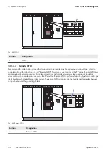
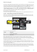
Figure 64: Insulation monitoring device
Position
Designation
A
Insulation monitoring device
A measuring circuit and a relay with a change-over contact are integrated in the insulation monitoring device.
The insulation monitoring device is connected between the PV voltage and the grounding conductor. The contacts of
the relay are routed to the customer terminal plate and can be used by the customer to trip a signal light or siren. The
characteristics of the relay are indicated in the circuit diagram.
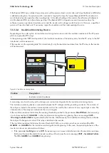
If the insulation resistance falls below the warning threshold specified in the parameter
RisoCtlWarn
, the measuring
circuit closes and the LED
ALARM1
on the insulation monitoring device is glowing. The error message
3601‒
Warning insulation failure
is generated by the inverter. Simultaneously, the insulation monitoring device activates
the relay with change-over contact. This relay is installed in the inverter.
If the insulation resistance falls below the error threshold (1 kΩ), an insulation error has occurred and the LEDs
ALARM1
and
ALARM2
on the insulation monitoring device are glowing. In this case, the operating behavior of the
inverter can be set via parameters as follows:
• If the parameter
IsoErrIgn
is set to
Off
, the measuring circuit issues a disturbance when the insulation resistance
falls below the error threshold, the inverter switches off and issues the error message
3501 - Insulation Failure
.
The LEDs
ALARM1
and
ALARM2
are glowing.
13 Function Description
SMA Solar Technology AG
System Manual
187
MVPS22JP-SH-en-11
Summary of Contents for 1000-1SC
Page 257: ......

