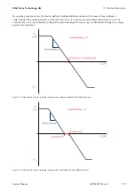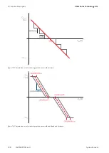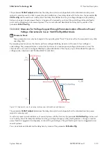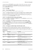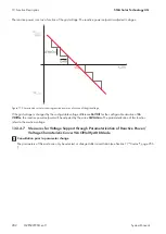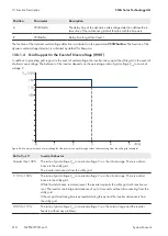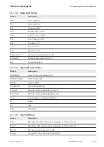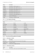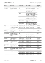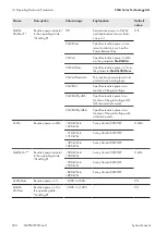
The tripping threshold is defined by the parameter
FRTDbVolNomMax
.
13.6
Cascade Control
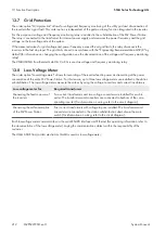
The order option "Cascade control" allows for staggered reconnection of several medium-voltage switchgears after a
grid failure or maintenance work. For this option, the following changes are implemented by default:
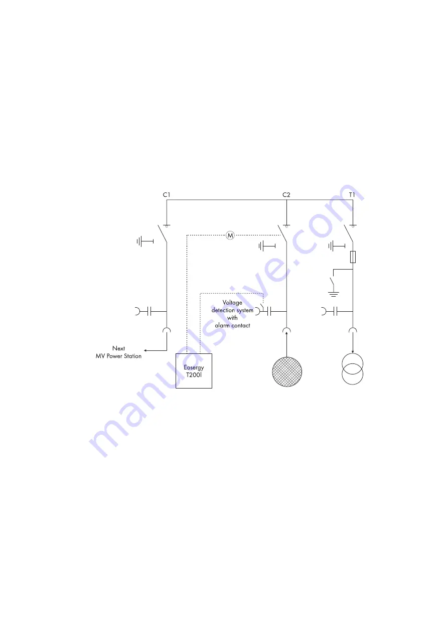
• The medium-voltage switchgear is motorized in the middle cable panel.
• The capacitive voltage detection system of the medium-voltage switchgear is equipped with an alarm contact.
• A control device is integrated in the medium-voltage compartment of the MV Power Station.
Up to four medium-voltage switchgears can be connected in this staggered manner. The crucial factors are the limited
ampacity of the load-break switch in the cable panel and the sum of the high start-up currents of the MV transformers.
This makes it possible to use an MV Power Station with cascade control to control four further MV Power Stations in an
automated way.
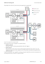
Figure 87: Simplified block circuit diagram of the medium-voltage switchgear with cascade control
The control device is connected to the middle cable panel of the medium-voltage switchgear and controls an
integrated motor. Furthermore, the control device is connected to the alarm contact of the voltage detection system
integrated in the medium-voltage switchgear. The alarm contact of the voltage detection system is used for connecting
and disconnecting the middle cable panel. The switching limiting value for the voltage detection system is set in
accordance with IEC 61 243-5. The voltage is measured upstream the load-break switch in the middle cable panel.
If the voltage falls below the permitted switching limit, a signal is transmitted to the control device and the middle cable
panel of the controlled medium-voltage switchgear is disconnected with a delay of three seconds. If the voltage
detection system measures a voltage exceeding the permitted switching limit, a signal is transmitted to the control
device and the middle cable panels of the connected medium-voltage switchgears are connected gradually. The time
delay for gradual connection must be set in accordance with the grid operator's specifications. The time delay is set to
ten seconds by default.
The control device is monitored and configured via the serial RS232 interface, a USB port and the Ethernet network by
means of a web-based user interface (for operating information, refer to the documentation of the control device).
Laying the communication cables is within the responsibility of the customer.
The Easergy T200I from Schneider Electric is used as control device.
13 Function Description
SMA Solar Technology AG
System Manual
211
MVPS22JP-SH-en-11
Summary of Contents for 1000-1SC
Page 257: ......

