16.3
Installation Information
16.3.1 Torques
Torques of the power connections:
Type of terminal lug
Torque
Tin-plated aluminum terminal lug on copper bar
37 Nm
Tin-plated copper terminal lug on copper bar
60 Nm
Tin-plated aluminum or copper terminal lug on aluminum bar
37 Nm for M12
10 Nm for M8
Torques at panels, covers and grounding conductor:
Position
Torque
Grounding conductors on the kick plates
8 Nm to 10 Nm
Mounting the kick plates
2 Nm to 3 Nm
Grounding conductor on the roof
14.2 Nm
Mounting the ventilation grids on the roof
20 Nm
Protective covers
5 Nm
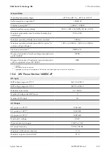
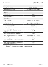
16.3.2 Reduction of DC Input Currents for DC Fuses
The DC inputs are fused with LV/HRC fuses. Thermal stress and alternating loads result in reduction factors which must
be taken into account when designing the DC cables.
The reduction factor 0.70 is applicable for regions where maximum ambient temperatures of 40°C are expected. If
higher ambient temperatures are expected, a reduction factor of 0.64 must be used.
Fusing
Maximum DC short-circuit current I
SC_STC
(reduction factor 0.64 at ambient tem-
peratures exceeding 40°C)
Maximum DC short-circuit current I
SC_STC
(reduction factor 0.70 at ambient tem-
peratures up to and including 40°C)
125 A
80.0 A
87.5 A
160 A
102.4 A
112.0 A
200 A
128.0 A
140.0 A
250 A
160.0 A
175.0 A
315 A
201.6 A
220.5 A
400 A
256.0 A
280.0 A
When selecting the fuse size, always consider the short-circuit current of the connected PV array at standard test
conditions (I
SC_STC
).
The reduction factors apply for a maximum irradiation of 1,200 W/m
2
(hourly average value of the horizontal global
radiation). In case the irradiation is higher, the reduction factor must be adapted linearly.
16 Appendix
SMA Solar Technology AG
System Manual
MVPS22JP-SH-en-11
252
Summary of Contents for 1000-1SC
Page 257: ......

