5.3.1.3
Opening the Drain Orifices in the Inverter Compartment
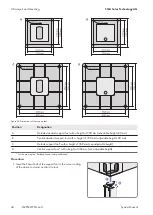
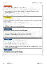
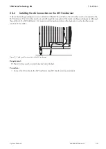
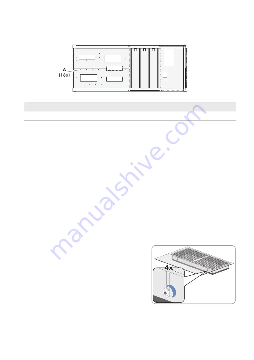
The drain orifices in the inverter compartment are sealed with plugs and must be opened prior to installation.
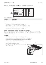
Figure 28: Position of the drain orifices
Position
Designation
A
Drain orifice
Procedure:
1. Open the inverter compartment (see Section 12.1, page 159).
2. Disassemble the panels of the inverters (see Section 12.3.1.2, page 164).
3. Remove the plugs from the drain orifices in the floor of the station container.
4. Close the inverter compartment (see Section 12.1, page 159).
5.3.2
Mounting the Exhaust Duct under the Inverters
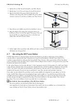
The exhaust ducts must be mounted under the inverters prior to installation. The exhaust duct is positioned on the
bottom side of the ventilation plate. The warm exhaust air from the inverters is evacuated through the exhaust ducts
under the MV Power Station.
Procedure:
1. Open the inverter compartment (see Section 12.1, page 159).
2. Disassemble the panels on the inverter cabinet (see Section 12.3.1.2, page 164).
3. On the front side of the inverter, remove the ventilation plate from the inverter.
4. Remove the screws of the cover plate under the inverter.
5. Remove the cover plate from the station container. The cover plate and the screws are no longer needed.
6. Push the ventilation plate into the inverter.
7. Loosen the four screws on the exhaust duct on the bottom side
of the ventilation plate.
5 Installation
SMA Solar Technology AG
System Manual
53
MVPS22JP-SH-en-11
Summary of Contents for 1000-1SC
Page 257: ......

