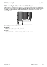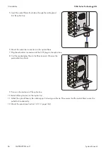
3. Connect the cables in accordance with the circuit diagram (see Section 12.6, page 175).
4. Secure the cables on the cable support rail. This will prevent the cables from being pulled out inadvertently.
5. Mount the panels (see Section 12.3.1.2, page 164).
5.7.2.9
Connecting the Data Cable of the Sunny String-Monitor
For an optimum supply voltage, it is recommended to connect two insulated conductors each in the terminals of the
supply voltage and of the grounding.
Cable requirements:
☐ The supply voltage and the communication connection must be combined in one cable.
☐ The cable used must be shielded.
☐ Recommended cable type: Li2YCYv (TP) 4 x 2 x 0.5 mm².
Procedure:
1. Disassemble the panels (see Section 12.3.1.2, page 164).
2. Insert the cables (see Section 12.4.3, page 171).
3. Connect the cables in accordance with the circuit diagram (see Section 12.6, page 175).
4. Secure the cables on the cable support rail. This will prevent the cables from being pulled out inadvertently.
5. Mount the panels (see Section 12.3.1.2, page 164).
5.8
Completion Work
5.8.1
Closing the Base Plates on the Inverter
Requirement:
☐ All cables must be inserted in and connected to the MV Power Station.
Procedure:
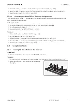
1. Insert the base plates under the inverter. The base plates must be aligned as close as possible to each other.
2. Tighten the base plates. Ensure that the enclosure openings
close tightly.
5 Installation
SMA Solar Technology AG
System Manual
71
MVPS22JP-SH-en-11
Summary of Contents for 1000-1SC
Page 257: ......


