background image

6.5.14 Configuring System Settings via XML File

6.5.14.1 Uploading the File custom.xml

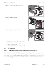
When you upload the file 

custom.xml

 to the user interface, the communication unit checks the file to ensure that the

values entered are valid and accurate, and adopts the settings at the next reset of the communication unit.

Correct network settings

While uploading, the communication unit checks the XML file 

custom.xml

 for validity and accuracy of the

entered values. The accuracy of the network settings is not checked.

• Ensure that the file 

custom.xml

 includes the correct network settings.

Procedure:

1. Create the file 

custom.xml

 with the required settings (see Section 16.4, page 253).

2. Log into the user interface as an installer (see Section 12.8.1, page 177).

3. Select 

Sunny Central > Settings > System

.

4. Select [

Browse

] in the field 

Upload settings (custom.xml)

.

5. Double-click on the file 

custom.xml

 in the open dialog box.

6. Select the button [

Upload

].

☑ The message 

Do you really want to apply the customer-specific settings

 is displayed.

✖ The message 

The settings have not been activated because the file has an invalid format or invalid

entries.

 is displayed?

• Click on the   symbol.

• Read off the error in the open dialog box and correct the file 

custom.xml

.

• Ensure that the file 

custom.xml

 is valid and correct.

7. Select the button [

Confirm

].

☑ The following message is displayed: 

The settings were successfully saved. The settings will become

effective by carrying out a reset to default settings

.

8. To enable the settings in the file 

custom.xml.

, the communication unit must be reset to the default settings (see

Section 6.5.15, page 93).

9. To log off from the user interface, select the button [

Logout

].

6.5.14.2 Downloading the File custom.xml

The file 

custom.xml

 that you have uploaded can also be downloaded.

Procedure:

1. Log into the user interface as an installer (see Section 12.8.1, page 177).

2. Select 

Sunny Central > Settings > System

.

3. Click on the link 

(custom.xml)

 in the field 

Upload settings (custom.xml)

.

4. Choose a storage location for the file and save it.

5. To log off from the user interface, select the button [

Logout

].

6.5.14.3 Deleting the File custom.xml

You can delete the file 

custom.xml

 via the user interface. If you have enabled your personal settings via the file

custom.xml

 before deleting it, these settings will remain effective.

6 Commissioning

SMA Solar Technology AG

System Manual

MVPS22JP-SH-en-11

92

Summary of Contents for 1000-1SC

Page 1: ...System Manual MEDIUM VOLTAGE POWER STATION 500SC JP 630SC JP 800SC JP 1000SC JP 1250SC JP 1600SC JP MVPS22JP SH en 11 101817 00 01 Version 1 1 ENGLISH...

Page 2: ...nations do not mean that a product or brand is not a registered trademark Modbus is a registered trademark of Schneider Electric and is licensed by the Modbus Organization Inc QR Code is a registered...

Page 3: ...rcuitry Principle of the MV Power Station 26 3 13 Operating and Display Elements 27 3 13 1 Switch in the Inverter 27 3 13 1 1 Key Switch 27 3 13 1 2 AC Disconnection Unit 28 3 13 1 3 DC Switchgear 28...

Page 4: ...the Station Container 57 5 5 Installing the AC Connection 58 5 5 1 Installing the AC Connection on the Medium Voltage Switchgear 58 5 5 2 Installing the AC Connection on the MV Transformer 59 5 6 Inst...

Page 5: ...ive Power Ramp Up 83 6 5 7 2 Setting the Frequency Dependent Active Power Limitation 84 6 5 7 3 Setting the Frequency Independent Active Power Limitation 84 6 5 7 4 Setting Reactive Power Control 85 6...

Page 6: ...Disconnecting the MV Transformer 101 7 6 Disconnecting the MV Power Station 101 7 7 Reconnecting the MV Power Station 102 7 8 Reconnecting the MV Transformer 102 7 9 Reconnecting the Inverter 103 7 9...

Page 7: ...in the Medium Voltage Compartment 115 9 3 Troubleshooting in the Inverter 118 9 3 1 Activating Alert in the Event of a Fault 118 9 3 2 Reading Off Disturbance Messages 119 9 3 2 1 Reading Off Error M...

Page 8: ...ation Grids 146 10 5 3 Cleaning the Ventilation Plate 146 10 5 4 Checking the Fuses Disconnection Blades 147 10 5 5 Checking the Bolted Connections of the Power Cabling 147 10 5 6 Checking the Surge A...

Page 9: ...ates 179 13 1 2 Stop 180 13 1 3 Grid Monitoring 180 13 1 3 1 Monitoring the Grid Voltage 180 13 1 3 2 Monitoring the Power Frequency 181 13 1 4 Grid Monitoring Time Reached 181 13 1 5 Startup 182 13 1...

Page 10: ...cteristic Curve VArCtlVolHystDbA Mode 199 13 3 4 Q at Night 200 13 3 4 1 No Q at Night Off Mode 200 13 3 4 2 Q at Night with Operation Command via Modbus Protocol VArCtlCom Mode 200 13 3 4 3 Q at Nigh...

Page 11: ...2 Sunny Central String Monitor Controller 236 14 2 3 Sunny String Monitor 237 14 2 4 Zone Monitoring 239 15 Technical Data 241 15 1 MV Power Station 500SC JP 241 15 2 MV Power Station 630SC JP 242 15...

Page 12: ...Training in how to deal with the dangers and risks associated with installing and using electrical devices and systems Training in the installation and commissioning of electrical devices and systems...

Page 13: ...ected or pressed Select Start detection 1 6 Nomenclature The products installed on the Medium Voltage Power Station such as the inverter or the MV transformer are referred to as devices Complete desig...

Page 14: ...amage Alterations to the product e g changes or modifications are only permitted with the express written permission of SMA Solar Technology AG Unauthorized alterations will void guarantee and warrant...

Page 15: ...ve cables results in death or serious injury due to electric shock Prior to connecting the DC cables ensure that the DC cables are voltage free Wear suitable personal protective equipment for all work...

Page 16: ...d before performing any work or making any adjustments All work and adjustments on the MV transformer must be performed by a duly authorized person Wear suitable protective equipment for all work Dang...

Page 17: ...o not touch or access the roof of the medium voltage switchgear when medium voltage is connected When switching operations are performed all persons that are not on the service platform have to keep a...

Page 18: ...ostatic discharge can damage or destroy electronic components Observe the ESD safety regulations when working on the product Wear suitable personal protective equipment for all work on the product Dis...

Page 19: ...ding to the specific project requirements The MV Power Station may contain one or two inverters Figure 1 Design of the PV power plant with MV Power Station example 3 2 Design of the MV Power Station F...

Page 20: ...Transformer for internal power supply The transformer for internal power supply provides the supply voltage for the MV Power Station and its devices It is con nected to the low voltage side of the MV...

Page 21: ...the inverter from the PV array E SC COM The SC COM is the communication unit of the inverter The SC COM estab lishes the connection between the inverter and the system operator F AC disconnection uni...

Page 22: ...ger The tap changer makes it possible to adjust the transmis sion ratio of the MV transformer optional 3 6 Devices of the Medium Voltage Compartment A H F E D G B C Figure 6 Devices of the medium volt...

Page 23: ...de control the middle cable panel is additionally equipped with a motor drive A B C 36 kV C B A 24 kV Figure 7 Devices of the medium voltage switchgear using the examples of a 24 kV switchgear and a 3...

Page 24: ...8 Optional devices of the station subdistribution example Position Designation A Low Voltage Meter B Voltage and frequency monitoring relay for order option Grid protection 3 9 Devices of the Communit...

Page 25: ...ater The rain water is heavier than the oil and runs through the oil separator whereas the oil remains in the oil tray An oil drain valve must be mounted at the oil tray in order to remove oil that ha...

Page 26: ...Position of the transformer for internal power supply Position Designation A Transformer for internal power supply 3 12 Circuitry Principle of the MV Power Station Figure 12 Circuitry principle of the...

Page 27: ...ere is sufficient irradiation and a valid utility grid connection the inverter switches to feed in operation If there is insufficient irradiation and the input voltage is therefore too low the inverte...

Page 28: ...ection unit is closed B Central switch position The AC disconnection unit was tripped and is open C Switch position off The AC disconnection unit is open 3 13 1 3 DC Switchgear The DC switchgear disco...

Page 29: ...r fans with order option Ambient temperature up to 50 C 55 C B Circuit breaker of the supply voltage of inverter 1 C Circuit breaker of the supply voltage of inverter 2 D Circuit breaker of the contac...

Page 30: ...of the transformer panel 3 13 4 Switch on the Control Device for Cascade Control For the order option Cascade control a control device for the medium voltage switchgear is integrated in the medium vo...

Page 31: ...nd the logged in user will be logged out By tapping the characters S M or A you can unlock the display again The touch display is divided into three areas Figure 19 Design of the touch display Positio...

Page 32: ...r is closed If you see this symbol between the symbol Inverter data and the symbol AC side the AC contactor is closed Switch on DC or AC side open If you see this symbol between the DC side symbol and...

Page 33: ...l displacement power factor cos Actual excitation type of the displacement power factor Settings Menu Symbol Designation Explanation Language selection Select this symbol to open the language selectio...

Page 34: ...plication software SC COM version SC COM software version Ser No inverter serial number Hardware hardware version and serial number of the SC COM Error ErrNo error number TmsRmg time until reconnectio...

Page 35: ...ad or write access to internal data drive CF flashing green Read or write access to external SD memory card H1 flashing green The SC COM is transmitting data to Sunny Portal FTP server glowing green T...

Page 36: ...eing overwritten flashing red 92 of the storage capacity of the internal memory card is used H5 glowing green An external memory card exists and less than 92 of its storage ca pacity is used glowing r...

Page 37: ...r connection Position LED Color Status Explanation A Link Activity green on Connection Link established flashing The SC COM is transmitting or receiving data Activity off No connection established 3 1...

Page 38: ...Explanation Tree view In the tree view the user interface shows the devices in the or der in which they are connected to the data bus Device view In the device view the user interface shows all devic...

Page 39: ...er from all angles Beware of a danger zone This warning symbol indicates a danger zone Be particularly vigilant and cautious when working on the product Warning regarding dan gerous voltage The produc...

Page 40: ...from the product Damage to the frame construction due to uneven support surface If the product is set down on uneven surfaces components may distort This may lead to moisture and dust penetration int...

Page 41: ...MV Power Station is marked on the station container Figure 24 Center of gravity symbol 4 3 Transporting the MV Power Station Using a Crane Requirements The crane and hoist must be suitable for the we...

Page 42: ...loaded on railroad cars with shock absorbers Procedure 1 Load the MV Power Station onto the means of transport see Section 4 3 page 41 2 Use container locks to secure the MV Power Station by at least...

Page 43: ...t is adjustable if necessary After the mounting process of the MV Power Station is completed the height of the standard support feet can no longer be adjusted Requirement To attach the support feet to...

Page 44: ...ght 20 mm C Outside support foot with a height of 368 mm non adjustable height D Central support foot with a height of 368 mm non adjustable height For the order option Earthquake and storm qualificat...

Page 45: ...s the support feet should be anchored to the foundation For the option Seismic and Storm Qualification stricter requirements apply to the foundations The MV Power Station comes with special support fe...

Page 46: ...ing a suitable means of transport Using a suitable means of transport transport the oil tray as close to the ground as possible Risk of injury if heavy service platforms are lowered too fast The servi...

Page 47: ...ht of the oil tray to the height of the MV Power Station Secure the oil tray against floating away if necessary 5 Unscrew the nuts from the stud bolts of the support feet for the service platforms and...

Page 48: ...ople pull the service platform forwards and down Use the handles on the service platforms 11 After opening the protective roof tighten the retainer on the roof and the container 12 Repeat steps 5 to 1...

Page 49: ...re working on the PV power plant ensure that no ground fault is present Wear suitable personal protective equipment for all work on the device Danger to life from electric shock due to live DC cables...

Page 50: ...near or on the service platforms Damage to the devices due to sand dust or moisture penetration Sand dust or moisture penetration can damage the devices of the MV Power Station or impair their functio...

Page 51: ...transformer compartment Section 5 3 3 page 54 Working in the compartment of the medium voltage switchgear Section 5 3 4 page 55 Inserting the cables Section 12 4 page 167 Grounding the station contain...

Page 52: ...aps Since there is tension on the tie down straps there is a risk of whiplash when they are released This can result in cuts or crushing of limbs Ensure that the tie down straps cannot whiplash Observ...

Page 53: ...r the inverters prior to installation The exhaust duct is positioned on the bottom side of the ventilation plate The warm exhaust air from the inverters is evacuated through the exhaust ducts under th...

Page 54: ...the tie down straps must be removed and the drain orifices must be opened Figure 29 Position of the drain orifices in the MV transformer compartment Position Designation A Drain orifice Risk of injury...

Page 55: ...areless handling of packaging material can lead to death by suffocation Remove packaging material carefully from the product Risk of injury when releasing the tie down straps Since there is tension on...

Page 56: ...159 2 Remove the desiccant bags from the station container Remove the cable ties around the desiccant bags using diagonal cutting pliers The desiccant bags are to be found at the following positions B...

Page 57: ...Station Container Equipotential bonding of the oil tray The supplied oil tray must be connected to the grounding busbar of the MV Power Station A Figure 30 Position of the grounding to the station con...

Page 58: ...surfaces again after cleaning 8 Connect the grounding cable for grounding the oil tray to the grounding bolt of the oil tray M13 torque 15 Nm 9 Connect the grounding cable for grounding the oil tray t...

Page 59: ...oltage switchgear and through the partition to the MV transformer It is recommended using plastic tubes without grooves in order to allow easier insertion of the cables Figure 31 Cable route for conne...

Page 60: ...s must be designed according to the temperature Temperature 95 C The width of the terminal lugs must exceed the washer diameter Washer diameter 32 mm This will ensure that the defined torques are effe...

Page 61: ...connection area with the non woven abrasive until they have a light metallic sheen 5 Clean all contact surfaces in the connection area using a clean cloth and ethanol cleaning agent and do not touch...

Page 62: ...erature 95 C The width of the terminal lugs must exceed the washer diameter The diameter of the washers for M12 screws is 32 mm The diameter of the washers for M8 screws is 20 mm This will ensure that...

Page 63: ...forwards 7 Secure the cables on the cable support rail This will prevent the cable from being pulled out inadvertently 8 Mount the protective covers see Section 12 3 1 1 page 163 9 Mount the panels s...

Page 64: ...ension and the minimum permissible bend radii of the optical fibers 2 Connect the patch panel to the network switch using the optical fiber patch cables included in the delivery bend radius 100 mm Obs...

Page 65: ...Damage to optical fibers due to too tight bend radii Excessive bending or kinking will damage the optical fibers Observe the minimum permissible bend radii of the optical fibers Procedure 1 Disassemb...

Page 66: ...glass fiber in the fiber reservoir Observe the permissible bend radii 9 Screw on the enclosure of the splice box 10 Reinstall the splice box on the top hat rail 11 Attach the optical fibers to the cab...

Page 67: ...er connector Damage to optical fibers due to too tight bend radii Excessive bending or kinking will damage the optical fibers Observe the minimum permissible bend radii of the optical fibers Procedure...

Page 68: ...optical fibers to the cable support rail using a cable tie This ensures that the optical fibers cannot be pulled out inadvertently 12 Mount the panels see Section 12 3 1 2 page 164 5 7 2 3 Connecting...

Page 69: ...AC contactor If the MV Power Station is delivered with order option AC contactor the fast stop input for the voltage and frequency monitoring relay is already assigned Thus connecting an external swi...

Page 70: ...4 Secure the cables on the cable support rail This will prevent the cables from being pulled out inadvertently 5 Mount the panels see Section 12 3 1 2 page 164 5 7 2 7 Connecting the Cable for the Sta...

Page 71: ...type Li2YCYv TP 4 x 2 x 0 5 mm Procedure 1 Disassemble the panels see Section 12 3 1 2 page 164 2 Insert the cables see Section 12 4 3 page 171 3 Connect the cables in accordance with the circuit dia...

Page 72: ...the medium voltage switchgear arc faults may occur during operation of the product which can result in death or serious injuries If arc faults occur in the medium voltage switchgear the pressure evac...

Page 73: ...ected to the MV Power Station DC side The PV array must be checked All cables of the PV array must be correctly connected to the Sunny String Monitors All cables of the Sunny String Monitors must be c...

Page 74: ...g are correctly connected Section 6 3 2 3 page 75 4 Ensure that the high current contacts made on the installation site are cor rectly connected Section 6 3 2 4 page 75 5 Ensure that the high current...

Page 75: ...Ensure that the cable type and cross section the number of cables and the labeling comply with the specifications in the schematic diagram Cable connection Ensure that the cable connection complies wi...

Page 76: ...rs are securely in place Connectors on the SC20cont Connectors on the inverter bridge Connectors on the communication unit Connectors on the hub Connectors on the router 6 4 Connection and Measurement...

Page 77: ...power supply 2 Switch on the transformer circuit breaker of the transformer for internal power supply 3 Check whether the supply voltage is within the permissible voltage range of the inverter If the...

Page 78: ...eport Use the DC and DC connection brackets as measuring points 2 Check that the DC voltages do not exceed the maximum DC voltage of the inverter If the DC voltages differ from one another or exceed t...

Page 79: ...of the medium voltage switchgear is equipped with a circuit breaker and a protective device The protective device must be configured in accordance with the voltage level and the size of the MV transfo...

Page 80: ...40 22 14 43 18 19 23 09 23 13 81 17 40 22 09 Manufacturer of the medium voltage switchgear Schneider Electric Type of the medium volt age switchgear FLUSARC Protective device VIP 45 24 94 12 73 16 04...

Page 81: ...the connected nodes The IP address to be configured in your computer depends on whether the computer is connected to the service interface of the inverter the control network or the monitoring network...

Page 82: ...rter to be accessible via the Internet so that you can access it for example directly from Sunny Portal you must configure port forwarding in your router This may require adjustment of the network por...

Page 83: ...s no indication of progress on the communication unit after three minutes cancel the search Make sure the data cable of each device is properly connected and repeat the search Procedure 1 Log into the...

Page 84: ...rol procedures agreed with the grid operator are parameterized If the inverter is operated with a Power Plant Controller ensure that the mode WCtlCom for active power limitation and the mode VArCtlCom...

Page 85: ...values meet the requirements for feed in operation and Q at Night operation Procedure 1 Make sure the inverter is in the operating state Stop 2 Call up the parameter overview see Section 12 8 3 page 1...

Page 86: ...fications as follows see Section 13 3 5 page 206 6 If SubVal has been selected enter the substitute values for normal feed in operation and for operation outside of normal feed in operation 7 In the p...

Page 87: ...etting the Grid Support 6 5 9 1 Setting Full and Limited Dynamic Grid Support FRT 1 Call up the parameter overview see Section 12 8 3 page 178 2 Set dynamic grid support with the parameter FRTEna 3 Se...

Page 88: ...l String Monitor Controller and the Inverter 1 Log into the user interface see Section 12 8 1 page 177 2 Select Data Detection 3 In the field Total number of devices to be detected enter the value 2 4...

Page 89: ...ct them via the communication unit see Section 6 5 11 5 page 89 If only some of the Sunny String Monitors have been detected contact the Service 6 5 11 5 Detecting the Sunny String Monitors via the Co...

Page 90: ...eld Use the and buttons to change the time zone 6 Confirm your entry by selecting 6 5 12 3 Selecting the Display Format 1 Select 2 Select 3 Select the date format 4 Select the hour format 5 Select the...

Page 91: ...e user interface select Logout 6 5 13 4 Changing the Password for the User Groups The user interface distinguishes between the user groups user and installer To change the password for the installer u...

Page 92: ...invalid format or invalid entries is displayed Click on the symbol Read off the error in the open dialog box and correct the file custom xml Ensure that the file custom xml is valid and correct 7 Sele...

Page 93: ...data PV system identifier in Sunny Portal If you reset all settings all settings for logging into Sunny Portal will also be deleted If you restart the communication unit after the reset without chang...

Page 94: ...to electric shock or electric arc if live components are touched If the MV Power Station and its devices are not correctly disconnected dangerous voltages may be present in the components which if tou...

Page 95: ...see Section 17 Contact page 256 5 Reset the hygrostat to the initial value To do this press the selector switch back towards the hygrostat The initial value of the hygrostat is indicated in the circu...

Page 96: ...with open covers or doors Danger to life due to electric arcs if measuring device is not connected correctly If the measurement points are incorrectly contacted this can cause an electric arc Electri...

Page 97: ...pairment due to high frequency noises of the inverter The inverter generates high frequency noises when in operation This can result in hearing impairment Wear personal protective equipment for all wo...

Page 98: ...ter 4 MV transformer 5 Medium voltage switchgear 6 Higher level medium voltage switchgear string ring or transfer station A Disconnection device of the DC subdistribution or the DC main distribution B...

Page 99: ...ting the inverters from the supply voltage switch off the circuit breakers Voltage Supply SC1 and Voltage Supply SC2 2 For disconnecting the Communit and its lighting from the supply voltage switch of...

Page 100: ...ate any adjacent live components 6 Remove the protective covers over the fuses 7 Remove all fuses and disconnection blades from all fuse holders of the inverters Use an LV HRC fuse extractor 7 4 3 Dis...

Page 101: ...the AC voltage of the MV transformer Requirement The inverters must be switched off see Section 7 4 1 page 100 Procedure 1 Switch off the transformer panel of the medium voltage switchgear see documen...

Page 102: ...jacent live components 7 7 Reconnecting the MV Power Station Depending on how the PV power plant is designed the automatic reconnection function has to be activated in the superordinate MV Power Stati...

Page 103: ...l Voltages 1 Close the measurement and disconnect terminals 2 Switch on the motor protective circuit breakers of the grid monitoring 3 Connect any additional external voltage 4 If the supply voltage h...

Page 104: ...ution 7 9 4 Restarting the Inverter Turn the key switch to Start 7 10 Reconnecting the Supply Voltage of the Station Subdistribution 1 In case the transformer for internal power supply has been discon...

Page 105: ...from the product All work and switching operations on the medium voltage switchgear must only be performed by qualified persons wearing adequate personal protective equipment Operation failure of the...

Page 106: ...8 2 2 2 page 106 7 Enter your e mail address in the field Operator e mail Sunny Portal will send the access data to this e mail address 8 Select the button Save 9 Select Sunny Central Info 10 Select R...

Page 107: ...to Sunny Portal or the external FTP server fails the communication unit will make further attempts to transmit the data Procedure 1 Log into the user interface see Section 12 8 1 page 177 2 Select Su...

Page 108: ...key 8 3 3 3 Activating Automatic Data Transmission via FTP Push The communication unit is equipped with an FTP push function With this function the data collected from your PV power plant can be uplo...

Page 109: ...on Download 6 Choose the save location 7 Select the button Save 8 3 4 2 Downloading Data in CSV Format Data saved in CSV format can be automatically imported into tables e g in Microsoft Excel The con...

Page 110: ...ation on Saving Data on a Memory Card You can save all the data collected from the inverter to a memory card The save to memory card feature is disabled by default If a memory card is inserted into th...

Page 111: ...the Memory Capacity Available on the Memory Card 1 Log into the user interface see Section 12 8 1 page 177 2 Select Sunny Central Info 3 In the field Sunny Portal Buffer Load you can see the space ava...

Page 112: ...s document All safety information must be observed Do not touch any live components of the inverter or the medium voltage grid Comply with all applicable safety regulations for handling medium voltage...

Page 113: ...FDI and Insulation Monitoring Device Ground fault monitoring does not provide protection from personal injury Ground fault monitoring and the insulation monitoring device enable the PV array to be swi...

Page 114: ...ZIP File with Service Information In order to help you quickly and effectively a ZIP file containing service information may be required This ZIP file can be downloaded from the user interface The fil...

Page 115: ...Troubleshooting in the Medium Voltage Compartment Error Cause and corrective measure Supply voltage is not present If a transformer for internal power supply is present The transformer for internal po...

Page 116: ...e Corrective measures Replace the EMC filtering device Contact the Service see Section 17 page 256 The cabling is damaged Corrective measures Ensure that the cabling is intact The lighting in the medi...

Page 117: ...ge 256 The voltage supply of the MV Power Station failed Corrective measures Ensure that the supply voltage is present see error Supply voltage is not present The cabling is damaged Corrective measure...

Page 118: ...s in the PV power plant and minimizes downtimes The alert is deactivated upon delivery Communication unit reports an error type event after two averaging intervals The communication unit reports error...

Page 119: ...ue view 3 To display the delay time select the instantaneous value TmsRmg in the instantaneous value view 4 To display the error message select the instantaneous value Msg in the instantaneous value v...

Page 120: ...rface see Section 12 8 1 page 177 3 Select the parameter Ackn in the device displaying the error and set to Ackn 4 Select the button Save 9 3 4 Remedial Action in Case of Disturbances 9 3 4 1 Inverter...

Page 121: ...ed in How long the inverter remains in this state depends on the system specific influencing factors Once the time has elapsed the disturbance is no longer shown on the touch display The inverter then...

Page 122: ...he grid monitoring time is complied with Certain errors such as grid errors cause the inverter to shut down In this case the instantaneous value TmsRmg indicates the time for which the inverter monito...

Page 123: ...high Power frequency disturbance de tected by redundant monitoring 30 s 30 s 0506 The inverter has detected a stand alone grid and has disconnected from the utility grid W W Check power frequency 0801...

Page 124: ...toring 30 s 30 s 0204 Grid voltage is too low Undervolt age detected by standard monitor ing 30 s 30 s 0205 Grid synchronization not possible 30 s 30 s 0404 Frequency change per second too high for gr...

Page 125: ...tion monitoring device has measured a too low ground ing resistance C C Check the PV array for ground faults 3502 The GFDI has tripped C C Check the PV array for ground faults 3504 The insulation moni...

Page 126: ...igh 15 min 30 min Check the DC voltage Check the module wiring and system design 3404 Open circuit voltage is too high Disturbance detected by standard monitoring 15 min 30 min 3406 The DC voltage is...

Page 127: ...g and system design 4003 Reverse currents detected in the PV array or DC connection polarity reversed 30 s Q Check the PV modules for short circuits Check the module wiring and system design Check the...

Page 128: ...tner 6418 Overtemperature of the inverter bridge 5 min 15 min Contact Service partner 6422 Inverter bridge in undefined state 30 s 5 min Contact Service partner 6423 Overtemperature in the switch cabi...

Page 129: ...offline capacitor test Q Q x Contact Service partner 6501 Interior temperature of inverter is too high 30 s 1 min Check function of the fans Clean the fans Clean clogged fan inlets and ventilation pl...

Page 130: ...y switching state of the AC contactor 30 s Q Contact Service partner 7708 Faulty switching status of Re mote GFDI W W Contact Service partner 7709 90 of switch cycles of the DC switchgear reached 10 s...

Page 131: ...ror and switch fast stop back on 9019 Defective fast stop 30 s C Check the fast stop cabling 9 3 4 6 Displaying Disturbance Messages for Active Power Limitation The instantaneous value P WModFailStt d...

Page 132: ...ve power setpoint has been selected OK A mode for specifying the reactive power setpoint has been selected and no error is present ComFail The mode VArCtlCom or PFCtlCom has been selected and the expe...

Page 133: ...e to electrostatic discharge Electrostatic discharge can damage or destroy electronic components Observe the ESD safety regulations when working on the product Wear suitable personal protective equipm...

Page 134: ...rform an optical inspection Section 10 4 1 page 140 Check whether the protective grids in front of the transformer compartment are in tact Check the doors and structural components of the door frame f...

Page 135: ...carbon deposits from accumulating on the converter contacts Remove any rust patches and repaint Check and clean the cable entries protective device contact thermometer and control ele ments Check the...

Page 136: ...2 3 2 Medium Voltage Switchgear Maintenance under voltage free conditions Task See Perform a 12 months maintenance Section 10 2 2 4 page 136 Check the interlocking function Documentation for the medi...

Page 137: ...ding off error messages and warnings Section 9 3 2 page 119 Checking the AC disconnection unit Section 10 5 11 page 154 Maintenance under voltage free conditions Task See Performing an optical inspect...

Page 138: ...10 2 5 Maintenance Work Every 10 Years Medium voltage switchgear Maintenance under voltage free conditions Task See Perform a 12 months maintenance Section 10 2 2 4 page 136 Perform a 24 months maint...

Page 139: ...ic article number contact us see Section 17 Contact page 256 10 3 2 Demand Based Repairs Inverter Task Interval Replace key switch In case of severe signs of wear Replace surge arrester If tripped Rep...

Page 140: ...rc if live components are touched If the MV Power Station and its devices are not correctly disconnected dangerous voltages may be present in the components which if touched will result in death or se...

Page 141: ...e not correctly disconnected dangerous voltages may be present in the components which if touched will result in death or serious injury Disconnect the MV Power Station see Section 7 6 page 101 After...

Page 142: ...he side panel seals display any damage in the sealing area If seals are damaged contact us see Section 17 Contact page 256 10 4 4 Checking the Latches Door Stops and Hinges Required maintenance materi...

Page 143: ...ion to repair damage on the zinc plated steel frame in the base area e g LZ 09 Observe the relevant instructions of the manufacturer Position RAL color Color Roof RAL 7004 Signal gray Base RAL 7004 Si...

Page 144: ...with connection terminals at the upper end Position of the indicators Type of inverter bridges Number of indicators 1 to 17 with connection terminals at the upper end 17 10 to 17 without connection t...

Page 145: ...he product can get very hot during operation Touching these components can cause burns Observe the warnings on all components During operation do not touch any components marked with such warnings Aft...

Page 146: ...a brush 3 Vacuum the ventilation grids or clean them with a brush 4 Check the ventilation grids for visible damage Replace the ventilation grids if required 5 Mount the ventilation grids see Section...

Page 147: ...he capacitors to discharge completely Ensure that the MV Power Station and its devices are voltage free Procedure 1 Check the fuses disconnection blades and tension springs for any discoloration or ch...

Page 148: ...re securely in place If bolted connections are loose tighten them using a torque wrench 3 Check the insulation and connections for any discoloration or change in appearance If insulation and connectio...

Page 149: ...for testing are included in the user manual of the testing device If the surge arrester is defective replace it 10 5 7 Checking the Fans Danger to life due to electric shock or electric arc if live c...

Page 150: ...erter Position Order number Designation A 86 029687 Use hearing protection B 86 05200 Beware of dangerous voltage C 86 79615 Beware of a danger zone D 86 003303 Risk of lethal electric shock due to ac...

Page 151: ...due to modified settings K 86 0043553 Risk of lethal electric shock due to active power source L 86 003306 Plant protected by conductors M 86 003305 Incorrect connection leads to destruction of the de...

Page 152: ...If necessary you can order the labels using the order number stated above Contact us see Section 17 page 256 10 5 9 Checking the Heating Elements and Hygrostat Figure 46 Position of the heating elemen...

Page 153: ...Set the hygrostat to the minimum value To do this pull the selector switch out slightly Tip the hygrostat is adjusted correctly if the relay of the hygrostat emits an audible click 4 Check whether th...

Page 154: ...L1 and N The voltage is approximately 230 V Voltage deviates significantly Contact Service partner 4 Measure the voltage at the supply voltage output of the UPS at X400 terminal 5 and X402 terminal 5...

Page 155: ...njury due to electric shock After switching off the inverter wait at least 15 minutes before opening it to allow the capacitors to discharge completely Wear suitable personal protective equipment for...

Page 156: ...table personal protective equipment for all work on the product All work must be carried out in accordance with this document All safety information must be observed Do not touch any live components o...

Page 157: ...dicating the position On If the DC load break switch is not switched on or not indicating the position On contact see Section 17 Contact page 256 8 Switch the inverter to Stop 9 Test the switching pro...

Page 158: ...l disposal services for information on optimum material utilization and environmentally friendly disposal For further information on disposal and recycling refer to the respective documentation of the...

Page 159: ...e doors of the station container To access the medium voltage switchgear and the Communit or the rear sides of the inverter or to perform maintenance work you must unlock and open the doors of the sta...

Page 160: ...sealing mechanisms on the left hand door handle Turn the sealing mechanisms clockwise 4 Pull the left hand door handle up and out 5 Open the doors and make sure they cannot be closed 12 Periodic Actio...

Page 161: ...door handle Turn the sealing mechanisms counterclockwise 4 Push the right hand door handle in towards the door and press down 5 Lock the two sealing mechanisms on the right hand door handle Turn the...

Page 162: ...own too fast or dropped persons could be injured Have at least two people pull each service platform forwards and down Always wear suitable protective equipment Procedure 1 Open the doors of the mediu...

Page 163: ...ric shock or electric arc if live components are touched Switch off the inverter and wait at least 15 minutes before opening it to allow the capacitors to discharge completely Disconnect the inverter...

Page 164: ...the roof is not disassembled correctly the grounding conductors may be pulled out Take care not to damage the grounding conductors during disassembly Disassembling the panels 1 Remove the screws of t...

Page 165: ...the lower side of the right hand ventilation grid forwards to remove it 3 Release the screws of the left hand ventilation grid head size T40 4 Pull the lower side of the left hand ventilation grid fo...

Page 166: ...s Disassembling the kick plate 1 Loosen all screws of the kick plate 2 Carefully pull the kick plate forwards by 80 mm to 100 mm 3 Loosen the grounding strap from the kick plate 4 Remove the kick plat...

Page 167: ...tion 500SC JP 630SC JP 800SC JP C Base plate of the medium voltage switchgear 6 openings for single core cables maximum cable diameter 55 mm D Base plate with cable glands for the data cables and grou...

Page 168: ...tubes are used carry out the following steps Disassemble the base plate underneath the medium voltage switchgear Route protective tubes up to the base plates Allow for some reserve Close the protectiv...

Page 169: ...able gland Allow sufficient cable length to reach the connection point Lead the cable through the swivel nut of the cable gland Ensure that the thread of the swivel nut is facing downwards 12 4 2 Inse...

Page 170: ...2 Remove the rubber seal from the cable gland 3 Adjust the rubber seal to the diameter of the cable to be inserted Remove the appropriate number of sealing rings from the rubber seal Cable diameter Nu...

Page 171: ...rted Use the additional rubber seals included in the scope of delivery if necessary 5 Remove the sealing plugs from those rubber seals through which the cables are to be led 6 Lead the cables through...

Page 172: ...minal lug for grounding and DC cables Figure 54 Design of the connection with one two hole terminal lug Position Designation A Nut M12 B Spring washer 29 mm C Fender washer 32 mm D Connection busbar E...

Page 173: ...with one one hole terminal lug Position Designation A Nut M12 or M8 B Spring washer 29 mm for M12 or 18 mm for M8 C Fender washer 32 mm for M12 or 20 mm for M8 D Connection busbar E Tin plated one ho...

Page 174: ...sign of the connection with two two hole terminal lugs Position Designation A Nut M12 B Spring washer 29 mm C Fender washer 32 mm D Tin plated two hole terminal lugs E Connection busbar F Screw M12 12...

Page 175: ...onnection busbar F Screw M12 or M8 Additionally required mounting material not included in the scope of delivery Clean cloth Ethanol cleaning agent Procedure 1 Strip the cable insulation 2 Fit the cab...

Page 176: ...opening of the connection plug This will release the opening of the connection plug for the insulated conductors Insert the insulated conductors of the cable into the connection plug in accordance wit...

Page 177: ...symbol appears in the status info line 12 8 Settings on the User Interface of the Inverter 12 8 1 Logging Into the User Interface Default network settings for the service interface IP address 192 168...

Page 178: ...tically Procedure Select the button Logout 12 8 3 Accessing the Parameter Overview 1 Log into the user interface as an installer 2 Select Data Devices 3 Select the desired device from the list 4 Selec...

Page 179: ...ption 13 1 Operating States 13 1 1 Overview of the Operating States Figure 58 General overview of the operating states of the inverter 13 Function Description SMA Solar Technology AG System Manual 179...

Page 180: ...art Grid monitoring You can specify the thresholds and the delay time manually For voltage monitoring you can set two limits for overvoltage and two limits for undervoltage If the grid voltage increas...

Page 181: ...hresholds and delay times manually For frequency monitoring three thresholds can be configured for both overfrequency and underfrequency For example at an overfrequency of 50 5 Hz tripping can take pl...

Page 182: ...ion 13 1 6 1 MPP In the MPP operating state the inverter feeds power into the utility grid and operates permanently at the Maximum Power Point MPP Operation and the amount of power being fed in appear...

Page 183: ...chgear open automatically If the inverter shuts down because the feed in conditions are no longer met the inverter switches to the operating state Grid monitoring 13 1 8 Disturbance If a disturbance o...

Page 184: ...r switches from the current operating state to the operating state Stop Use of the remote shutdown will only be possible if the parameter ExlStrStpEna is set to On 13 2 2 Automatic Shutdown Functions...

Page 185: ...fault occurring on the ungrounded terminal will lead to high residual currents that cannot be interrupted by the ground fault monitoring unit Residual current monitoring in grounded systems In order t...

Page 186: ...ic error processing This reduces downtimes and avoids service calls due to temporary insulation errors such as when condensation occurs on the PV modules Remote GFDI is performed via a high performanc...

Page 187: ...ce A measuring circuit and a relay with a change over contact are integrated in the insulation monitoring device The insulation monitoring device is connected between the PV voltage and the grounding...

Page 188: ...sulation Monitoring it is possible to temporarily disable the PV array grounding and to check the insulation via the integrated insulation monitoring device Figure 65 GFDI and insulation monitoring Po...

Page 189: ...66 Remote GFDI and Insulation Monitoring Device Position Designation A Insulation monitoring device B Remote GFDI When the Remote GFDI is closed the PV array is grounded In this state the insulation r...

Page 190: ...nd if necessary repair the insulation and then acknowledge the error Type of insulation monitoring device used The insulation monitoring device used is the A ISOMETER iso PV1685 device supplied by Ben...

Page 191: ...r Limitation Off Mode The feed in power is limited to the parameter Pmax The parameter Pmax defines the inverter power at the feed in point and is adjusted to the local conditions during commissioning...

Page 192: ...ive power setpoint is received by the communication unit and transmitted to the inverter The setpoint is transmitted as a percentage value and converted to kVAr in the device If the inverter has not r...

Page 193: ...fed in 4 mA Qmax underexcited Start point of the characteristic curve The maximum amount of negatively excited reactive power is fed in 11 5 mA 0 kVAr Zero crossing of the characteristic curve No rea...

Page 194: ...ast valid mean value or 0 kVAr after restart Signal is in the invalid range 2 mA to 4 mA PFAbsMin underexcited The maximum amount of negatively excited reactive power is fed in 4 mA PFAbsMin underexci...

Page 195: ...n of active power On the basis of a linear characteristic curve with an upper and lower cap a displacement power factor cos can be regulated depending on the active power currently being fed in The st...

Page 196: ...f Q VDifTm the reactive power setpoint will be adjusted by the value Q VArGra The parameterization of this function refers to the medium voltage 13 3 3 11 Measures for Voltage Support through Paramete...

Page 197: ...e characteristic curve can be flexibly configured by parameterizing the slope a type of deadband through two voltage points and a hysteresis Figure 71 Characteristic curve for reducing reactive power...

Page 198: ...c curve for reducing reactive power with hysteresis Figure 74 Characteristic curve for reducing reactive power with deadband and hysteresis 13 Function Description SMA Solar Technology AG System Manua...

Page 199: ...ms voltage stabilizing measures in the event of overvoltage or undervoltage The parameterization is carried out by means of a reactive power voltage characteristic curve The characteristic curve can b...

Page 200: ...oDQ VArNom refers to Pmax If the calculated amount of reactive power exceeds the predefined value of QoDQmax it will be limited to QoDQmax If the calculated amount of reactive power falls below the pr...

Page 201: ...imitation of the reactive power to the parameter QoDQmax 13 3 4 6 Q at Night Depending on the Grid Voltage VArCtlVol Mode Consultation prior to parameter change The parameters of this mode can only be...

Page 202: ...of Q VDifTm the reactive power setpoint will be adjusted by the value Q VArGra The parameterization of this function refers to the medium voltage 13 3 4 7 Measures for Voltage Support through Paramete...

Page 203: ...ic curve The characteristic curve can be flexibly configured by parameterizing the slope a type of deadband through two voltage points and a hysteresis Figure 78 Characteristic curve for reducing reac...

Page 204: ...cteristic curve for reducing reactive power with deadband and hysteresis The parameter Q VArTmsSpnt determines the delay time which must elapse before the calculated reactive power setpoint is activel...

Page 205: ...f the slopes a type of deadband through two voltage points a hysteresis and the thresholds for activation Figure 82 Characteristic curve for reducing reactive power with deadband and hysteresis The pa...

Page 206: ...ation of the last value received In case of analog setpoints utilization of the last valid mean value SubVal Use of configured substitute values The use of the substitute values is recommended when se...

Page 207: ...The grid operator uses this network to transmit grid management specifications to the inverters The control network is used exclusively for grid management services that need to be transmitted and imp...

Page 208: ...function is activated via the parameter FRTEna The inverter behavior can be controlled via the parameter FRTMod The level of reactive current provided with full dynamic grid support is determined via...

Page 209: ...1 2 seconds with out disconnecting from the utility grid The requirement is that the ratio Vgrid V was at least 90 before the error occurred If the set grid monitoring time is exceeded during this pe...

Page 210: ...the inverter can work through without disconnecting from the utility grid example Ratio Vgrid V Inverter behavior Greater than 130 The ratio of grid voltage Vgrid to nominal voltage V is in the criti...

Page 211: ...ltage detection system integrated in the medium voltage switchgear The alarm contact of the voltage detection system is used for connecting and disconnecting the middle cable panel The switching limit...

Page 212: ...e inverter feed in power and recording of the power consumption of the entire MV Power Station For this reason up to three low voltage meters are installed in the station subdistribution The low volta...

Page 213: ...t continually calculates the mean values of the input currents and compares the current measured values with the mean values If an input current falls below the mean value by a user defined tolerance...

Page 214: ...limitation Name Display Description P WModFailStt Off No mode for active power limitation has been selected Ok A mode for active power limitation has been selected and no error is present ComFail The...

Page 215: ...ctive power is increased via the setpoint due to the DC voltage being too high AmpPvOptiprot For the order option Optiprotect the active power is limited due to switch currents being too high Errors a...

Page 216: ...ing AmpAC The reactive power is limited via an AC current limitation P The reactive power is limited due to the priority of the active power setpoint FrtLim The reactive power is limited due to the FR...

Page 217: ...nKeySwStrStp Status of key switch DInGfdi Status of GFDI DOutMntSvc State of the signal light Firmware Firmware version of operation control unit Firmware 2 Firmware version of digital signal processo...

Page 218: ...ning service information Name BfrSolIrr CardStt ExtSollrr Fb_SVMMode FeedInStt Firmware 3 Firmware 4 Firmware 5 Firmware 6 Firmware 7 Firmware 8 Firmware 9 Firmware CRC Firmware 2 CRC Firmware 5 CRC F...

Page 219: ...or all eight measuring channels 14 1 3 2 Internal Device Values Name Description Meldekontakt 1 Status of alarm contact 1 Meldekontakt 2 Status of alarm contact 2 Netz Adresse Network address of the S...

Page 220: ...has failed DevNotReachable I O module has not answered for at least 30 seconds StatusZone x No error ZoneValueLow The input has an input current which is too low ZoneValueFail For the input the input...

Page 221: ...al 800CP JP 880 kW P WNom Limitation of active power in 0 to 100 100 WCtlHzMod Activation of frequency dependent active power limitation Off Off CurveHys Procedure with hysteresis Curve Procedure with...

Page 222: ...l 630CP JP 0 kVAr 0 kVAr to 880 kVAr Sunny Central 800CP JP 0 kVAr QoDQmax Limitation of reactive power in the operating state Q at Night The reactive power can not exceed Qlimit 0 kVAr to 500 kVAr Su...

Page 223: ...NomAnIn The reactive power setpoint is im ported via an analog input PFCnst Manual specification of the dis placement power factor cos and excitation of the displace ment power factor via the param et...

Page 224: ...CtlVolHystDb Specifies reactive power as a function of the grid voltage Q f V characteristic curve VArCtlVolHysDbA Specifies reactive power as a function of the grid voltage with activation power Q VA...

Page 225: ...d OvExt UnExt Underexcited PF PFStop Displacement power fac tor cos at characteristic curve point 2 The lower limit is defined by the parameter PFAb sMin 0 5 to 1 The parameter should not fall be low...

Page 226: ...e dependent reactive power control 10 to 10 This parameter is only active if the parameter Q VArMod is set to VArCtlCol 0 Q VArGraNom Reactive power gradient 0 V to 22 0 V Sunny Central 500CP JP 0 V 0...

Page 227: ...e power SDLimComSrc Selection of the SDLimit source CAN Interface of the communication unit UART UART Via SMA Net P WSubVal Substitute value for ac tive power limitation out side of normal feed in ope...

Page 228: ...Q VArGraNomPo s Reactive power gradient at a positive change of nominal voltage 0 V to 44 06 V Sunny Central 500CP JP 0 V 0 V to 31 47 V Sunny Central 630CP JP 0 V to 25 04 V Sunny Central 800CP JP Q...

Page 229: ...t enter the installer password To view or change this parameter you must enter the installer password 14 2 1 2 Grid Monitoring and Grid Limits To change these parameters you must enter the installer p...

Page 230: ...55 Hz to 60 Hz For 60 Hz grid 59 4 Hz HzCtlOpMax Maximum connection fre quency 50 Hz to 55 Hz For 50 Hz grid 50 5 Hz 60 Hz to 65 Hz For 60 Hz grid 60 6 Hz HzCtlOpMaxR econ Maximum connection fre quenc...

Page 231: ...nd value of AC voltage measurement 1 V to 1 000 V 862 V NormAac Measuring range end value of AC current mea surement 1 A to 3 000 A 2 219 A ManResOvrVol Manual activation after overvoltage Off Deactiv...

Page 232: ...n the operating mode FRT_SDLWindV 0 to 10 Values between 0 and 2 are rec ommended For other values contact the Service see Sec tion 17 page 256 2 FRT2ArGraNo mLo Gradient of the FRT char acteristic cu...

Page 233: ...ial voltage to PvVtgStrLevMin for switching from insulation measurement to feed in operation 250 V to 250 V 0 V IsoDev Selection of insulation monitoring device isoPV3 isoPV3 isoPV1685 To view or chan...

Page 234: ...I SC 0 5 to 1 0 8 Serial Number Inverter serial number 0 to 2147483647 0 CntrySet Selection of valid power frequency Parameter can only be changed in the operating state Stop J50 For 50 Hz grid J60 Fo...

Page 235: ...0 Ofs_Cn tFanCab2 Offset for operating hours of interior fan 2 0 h to 2 147 482 h 0 Ofs_Cn tHtCab1 Offset for operating hours of internal heating element 1 0 h to 2 147 482 h 0 Ofs_Cn tHtCab2 Offset...

Page 236: ...ormat YYYYMMDD Tm Entry of current time 0 to 235959 Entered in the format HHMMSS TolGr1 Deviation of group 1 currents from mean value 5 to 100 Parameter exists for all six groups 13 MoniTmGr1On Start...

Page 237: ...String Moni tors AutoDetect_ SSMU Searches for all Sunny String Monitors and deletes previ ously detected Sunny String Monitors 0 DetectSSMU Retry Searches for undetected Sun ny String Monitors only...

Page 238: ...meter exists for all eight groups Configure the string settings preferably via the Sunny Cen tral String Monitor Controller 0 Monitoring1 Off End of monitoring of strings in group 1 0 00 a m to 11 59...

Page 239: ...he installer password 14 2 4 Zone Monitoring Name Description Value range Explanation Default value DcCfg AmpMax 1 Maximum current of input 1 0 A to 500 A 0 A DcCfg AmpMax 2 Maximum current of input 2...

Page 240: ...set tings Ackn Acknowledge errors Default no action Quit Acknowledgment of the present er ror AlarmEna Activation of the error analysis Default no action Off No error analysis Only measured value are...

Page 241: ...mum output current at 20 kV 16 A Transformer vector groups Dy11 YNd11 Displacement power factor cos 0 9 overexcited to 0 9 underexcited information based on inverter Efficiency Maximum efficiency 97 0...

Page 242: ...r Station 630SC JP DC Input MPP voltage range at 25 C 529 V to 850 V MPP voltage range at 50 C 500 V to 850 V Maximum input current 1350 A Number of independent MPP inputs 1 Number of DC inputs 9 AC O...

Page 243: ...ion of medium voltage compartment as per IEC 60529 IP23D Degree of protection of transformer compartment and in verter compartment as per IEC 60529 IP00 optional information based on inverter separate...

Page 244: ...elative humidity non condensing 15 to 95 Maximum operating altitude above mean sea level 1000 m Maximum operating altitude above MSL for option In stallation at high altitudes 1001 m to 2000 m 2001 m...

Page 245: ...Maximum efficiency 97 1 European weighted efficiency 96 8 General Data Width x height x depth 6058 mm x 2591 mm x 2438 mm Weight 14 t Operating temperature range 25 C to 40 C 25 C to 55 C Self consump...

Page 246: ...mber of independent MPP inputs 2 Number of DC inputs 18 AC Output AC power at 25 C 1375 kVA AC power at 40 C 1300 kVA AC power at 50 C 1250 kVA Nominal AC voltage 20 kV Optional nominal voltages 10 kV...

Page 247: ...tion of transformer compartment and in verter compartment as per IEC 60529 IP00 optional information based on inverter separated according to consumption of the inverter and standby power losses of th...

Page 248: ...E 50 Hz 60 Hz Maximum permissible value for relative humidity non condensing 15 to 95 Maximum operating altitude above mean sea level 1000 m Maximum operating altitude above MSL for option In stallati...

Page 249: ...r Figure 89 Scope of delivery of the station container Position Quantity Designation A 1 MV Power Station B 4 Support foot for the container corners C 2 Support foot for the container sides D 10 Suppo...

Page 250: ...tchgear D 1 Magnetic sign Do not switch E 1 Magnetic sign Earthed F 1 Documentation for the medium voltage switchgear Scope of delivery of the inverter The scope of delivery of the inverter is located...

Page 251: ...maintenance work when the environment is dry and free of dust If the installation maintenance or commissioning process is interrupted mount all enclosure parts and close all doors Damage to the frame...

Page 252: ...g the DC cables The reduction factor 0 70 is applicable for regions where maximum ambient temperatures of 40 C are expected If higher ambient temperatures are expected a reduction factor of 0 64 must...

Page 253: ...formation is displayed in the header of the user interface Config Key NetworkSettings_DhcpUsage1 Key Value False Value Config Here you can set the parameters and their corre sponding values see Sectio...

Page 254: ...netMask1 Sets the subnet mask for LAN2 255 255 0 0 255 255 0 0 NetworkSettings_DhcpUsage2 Activates DHCP for LAN3 With the True value all other settings of the IP addresses for LAN3 will be ignored Tr...

Page 255: ...he web server Do not use the following ports 21 23 502 8081 30100 80 NativeSettings_Language Sets the language of the user interface en English en Czech cs German de Greek el Spanish es French fr Ital...

Page 256: ...our service partner needs the following information in order to provide you with the necessary assistance Device type Serial number Type and number of PV modules connected Type of communication Error...

Page 257: ......

Page 258: ...SMA Solar Technology www SMA Solar com...

Reviews: