Installation Manual
SMC9-11TLRP-IA-en-51
35
SMA Solar Technology AG
6 Electrical Connection
Residual-current monitoring unit:
• If an external residual-current device is required, install a residual-current device which trips at a
residual current of 100 mA or higher (for details on selecting a residual-current device, see the
Technical Information "Criteria for Selecting a Residual-Current Device" at www.SMA-Solar.com).
SMC Classic_Überspannungskategorie
Overvoltage category
The inverter can be used in grids of installation category III or lower in accordance with IEC 60664-1.
That means that the inverter can be permanently connected to the junction box of a building. In case
of installations with long outdoor cabling routes, additional measures to reduce overvoltage category
IV to overvoltage category III are required.
STP klein SMC_Schutzleiter-Überwachung
Protective conductor monitoring:
The inverter is equipped with protective conductor monitoring which detects when no protective
conductor is not connected and disconnects the inverter from the electricity grid.
Requirements:
☐ The display language must be set to the required language (see section 7.4 "Changing the
☐ The connection requirements of the network operator must be met.
☐ The mains voltage must be in the permissible range. The exact operating range of the inverter is
specified in the operating parameters (see the Technical Description "Operating Parameters" at
www.SMA-Solar.com).
1. Disconnect the miniature circuit-breaker and secure against reconnection.
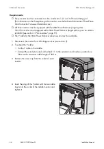
2. Loosen all screws and conical spring washers of the enclosure lid and remove the lid.
3. Remove the adhesive tape from the enclosure opening for the AC cable.
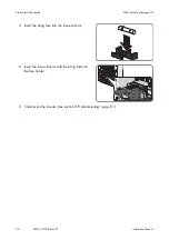
4. Attach the cable gland to the enclosure opening for the AC cable using a counter nut.
5. Strip the AC cable insulation.
6. Shorten L and N by 5 mm each.
7. Strip 18 mm of the L, N and PE insulation each.
8. Route the AC cable into the inverter through the cable gland. If necessary, slightly loosen the
swivel nut of the cable gland.
Connection of an additional protective conductor
In some countries an additional earthing is required. In each case, observe the local
applicable regulations.
• If an additional earthing is required, earth the inverter (see section 6.3.3 "Additional
Earthing of the Enclosure", page 37). The conductor cross-section muss correspond to the
cross section of the original protective conductor. This prevents touch current if the original
protective conductor fails.
6.3.2
Connecting the Inverter to the Electricity Grid
Summary of Contents for 10000TL
Page 2: ......
Page 6: ...Table of Contents SMA Solar Technology AG 6 SMC9 11TLRP IA en 51 Installation Manual ...
Page 94: ......
Page 95: ......


