background image

7  Commissioning

SMA America, LLC

48

SB3-5TLUS22-IA-en-12

Installation Manual

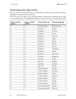
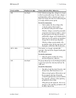
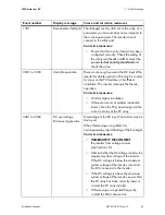
Possible Settings of the Rotary Switches

Here, you will find a list of possible rotary switch positions and which country data sets and display 
languages are represented by each position.
Each country data set contains various operating parameters, which can be individually set according 
to each country data set. The operating parameters can be read out using a communication product.

Rotary switch A 
position

Rotary switch B 
position

Country data set

Display language

0

0

Default settings

Default settings

0

1

Retained

English

0

2

Retained

German

0

3

Retained

French

0

4

Retained

Spanish

0

5

Retained

Italian

0

6

Retained

Greek

0

7

Retained

Czech

0

8

Retained

Korean

0

9

Retained

Portuguese

0

A

Retained

Dutch

0

B

Retained

Slovenian

0

C

Retained

Bulgarian

0

D

Retained

Polish

9

8

UL1741*

English

9

9

UL1741*

Spanish

9

A

UL1741*

French

C

0

Other standard

English

C

1

Other standard

German

C

2

Other standard

French

C

3

Other standard

Spanish

C

4

Other standard

Italian

C

5

Other standard

Greek

C

6

Other standard

Czech

D

0

Island mode 60 Hz

English

D

1

Island mode 60 Hz

German

Summary of Contents for 3000TL-US

Page 1: ...SB3 5TLUS22 IA en 12 Version 1 2 CA US PV Inverter SUNNY BOY 3000TL US 4000TL US 5000TL US Installation Manual ...

Page 2: ......

Page 3: ...indirect incidental or consequential damages under any circumstances The exclusion of implied warranties may not apply in all cases under some statutes and thus the above exclusion may not apply Specifications are subject to change without notice Every attempt has been made to make this document complete accurate and up to date Readers are cautioned however that SMA America LLC and SMA Solar Techn...

Page 4: ...tallation and operation of the product you must carefully read and follow all instructions cautions and warnings in this manual Warnings in this Document A warning describes a hazard to equipment or personnel It calls attention to a procedure or practice which if not correctly performed or adhered to could result in damage to or destruction of part or all of the SMA equipment and or other equipmen...

Page 5: ...are of hot surface The product can become hot during operation Do not touch the product during operation Electric arc hazards The product has large electrical potential differences between its conductors Arc flashes can occur through air when high voltage current flows Do not work on the product during operation Risk of fire Improper installation of the product may cause a fire Observe the operati...

Page 6: ...ons must conform with the laws regulations codes and standards applicable in the jurisdiction of installation SMA assumes no responsibility for the compliance or non compliance with such laws or codes in connection with the installation of the product The product contains no user serviceable parts For all repair and maintenance always return the unit to an authorized SMA Service Center Before inst...

Page 7: ...7 4 3 Type Labels 18 4 3 1 Sunny Boy 18 4 3 2 DC Disconnect 19 4 3 3 Symbols on the Type Labels 20 4 4 Display 21 4 5 Zigbee 23 4 6 Communication Interface 23 4 7 Secure Power Supply SPS 23 4 8 Fan Retrofit Kit 24 4 9 Arc Fault Circuit Interrupter AFCI 24 4 10 SD Card Slot 24 4 11 Varistors 24 4 12 SMA OptiTrac Global Peak 24 5 Mounting 25 5 1 Selecting the Mounting Location 25 5 2 Mounting the Wa...

Page 8: ... Array 40 6 5 Connecting the Secure Power Supply Module 43 6 6 Connecting the Zigbee Antenna 46 7 Commissioning 47 7 1 Making Settings via the Rotary Switches 47 7 1 1 Overview of the Rotary Switches 47 7 1 2 Changing the Country Data Set and the Display Language 49 7 1 3 Changing the Display Language 50 7 2 Commissioning the Inverter 51 8 Configuration 52 8 1 Changing the Country Data Set Using a...

Page 9: ...commissioning 75 12 1 Disassembling the Inverter 75 12 2 Packing the Inverter 76 12 3 Disposing of the Inverter 76 13 Technical Data 77 13 1 DC AC 77 13 1 1 Sunny Boy 3000TL US 77 13 1 2 Sunny Boy 4000TL US 78 13 1 3 Sunny Boy 5000TL US 79 13 2 Protective Devices 80 13 3 General Data 80 13 4 DC Disconnect 81 13 5 Climatic Conditions 81 13 6 Features 82 13 7 Torques 82 13 8 Data Storage Capacity 82...

Page 10: ...is document see Section 2 2 Skills of Qualified Persons page 12 Additional Information Links to additional information can be found at www SMA Solar com Symbols Nomenclature Document title Document type Capacitive Leakage Currents Technical information Shade Management Technical information Module Technology Technical information Symbol Explanation Indicates information that is important for a spe...

Page 11: ...1 400 nF for information on how to calculate the coupling capacity see Technical Information Capacitive Leakage Currents at www SMA Solar com All components must remain within their permitted operating ranges at all times The inverter is suitable for indoor and outdoor use Do not mount the inverter on flammable construction materials Do not mount the inverter in areas where highly flammable materi...

Page 12: ...of the inverter All work on the inverter may only be carried out by qualified persons Prior to performing any work on the inverter disconnect the inverter on the AC and DC sides see Section 10 Disconnecting the Inverter from Voltage Sources page 55 Only operate the inverter with the enclosure lid closed Do not open the upper enclosure lid Danger to life from electric shock due to damaged devices O...

Page 13: ...n cause damage to or destroy the inverter through electrostatic discharge Ground yourself before touching any components Observe local regulations All electrical installations must comply with the electrical standards applicable on site and the National Electrical Code ANSI NFPA 70 Installations in Canada must comply with the applicable Canadian standards ...

Page 14: ... the scope of delivery Item Quantity Description A 1 Inverter B 1 Wall mounting bracket for the inverter C 1 DC Disconnect D 1 Wall mounting bracket for the DC Disconnect E 1 Antenna for ZigBee communication optional F 3 M5 x 8 cheese head screw G 2 M5 x 12 cheese head screw H 1 M6 x 16 cheese head screw I 6 M5 conical spring washer including 1 spare K 1 M6 conical spring washer L 1 Installation m...

Page 15: ...PV inverter which converts the direct current of a PV array into grid compliant alternating current and feeds it into the utility grid Figure 2 Sunny Boy design Item Description A Cooling fins B Type label C Display D Lower enclosure lid screws E Antenna for ZigBee communication optional F LEDs G DC Disconnect H Lower enclosure lid I Upper enclosure lid ...

Page 16: ...he number of PV modules their orientation to the sun and shading Symbols on the Inverter Symbol Description Explanation Inverter This symbol defines the function of the green LED The green LED indicates the operating state of the inverter Observe the documentation This symbol defines the function of the red LED The red LED indicates an error Read this document for instructions on how to correct th...

Page 17: ...sconnect design Symbols on the DC Disconnect Item Description A Bracket for grounding the DC Disconnect enclosure B Rubber grommet for the enclosure opening C Bracket for hanging in the retainer D Type label 1 E Conduit knockouts F Type label 2 G Enclosure lid screws H Enclosure lid I Switch Symbol Description Explanation Equipment grounding conductor terminal Connection for the DC equipment groun...

Page 18: ...de of the enclosure Figure 4 Type label design The information on the type label is required for both safe operation of the inverter and for customer support from the SMA Service Line The type label must remain permanently affixed to the inverter Item Description Explanation A Model Inverter device type B S N Inverter serial number C Date of manufacture Inverter manufacture date month year D Devic...

Page 19: ... of the type label You will require the information on the type label to use the DC Disconnect safely and when seeking customer support from the SMA Service Line The type label must remain permanently affixed to the DC Disconnect Item Description Explanation A Product name B Item No DC Disconnect device type C Date of manufacture DC Disconnect manufacture date month year of the D Device specific c...

Page 20: ...e to hot surfaces The product can become hot during operation Avoid contact during operation Allow the product to cool down sufficiently before carrying out any work Wear personal protective equipment such as safety gloves Observe the documentation Observe all documentation that is supplied with the product ETL test mark The product has been certified by Intertek as being in accordance with the ap...

Page 21: ... of the inverter D Active functions Displays the activated or active functions for communication network system services or temperature derating E Line conductor Line conductor involved for the values displayed F Event number relating to the utility grid Event number of errors relating to the utility grid G Output voltage output current Displays output voltage and output current of a line conducto...

Page 22: ...tion 9 Display and LEDs page 53 Telephone receiver Indicates a fault that cannot be corrected on site Contact the SMA Service Line Wrench Indicates a fault that can be corrected on site by a qualified person Connection quality Indicates the quality of the ZigBee connection to other ZigBee devices Speedwire connection Indicates that communication via Speedwire is active and that there is a network ...

Page 23: ...communication products Depending on the type of communication RS485 or Speedwire the parameters and messages are displayed differently on the communication products You can adjust the country data set of the inverter before commissioning or within the first ten operating hours via the two rotary switches in the inverter All other operating parameters can only be set via communication products 4 7 ...

Page 24: ...C Disconnect is equipped with four varistors on the DC side Varistors are voltage dependent resistors that protect the inverter on the DC side against surge overvoltages It may be necessary under certain circumstances to replace the varistors see Section 11 5 Replacing DC Varistors page 73 Despite this protection against surge overvoltages PV arrays must be designed in such a way that the maximum ...

Page 25: ...thout the necessity for any auxiliary equipment such as scaffolding or lifting platforms Non fulfillment of these criteria may restrict servicing The mounting location should not be exposed to direct solar irradiation Direct solar irradiation can increase the operating temperature of the inverter As a result the inverter reduces its power output in order to remain within the operating limits To en...

Page 26: ...5 Mounting SMA America LLC 26 SB3 5TLUS22 IA en 12 Installation Manual Dimensions for mounting Figure 7 Wall mounting bracket dimensions ...

Page 27: ...recommended clearances to walls other inverters or objects This will prevent the inverter from reducing its power due to high temperatures If the inverter is mounted outdoors the clearance between the DC Disconnect and the floor must be 3 ft 914 mm This prevents the ingress of splashing water into the DC Disconnect Do not place or hang any objects on the inverter ...

Page 28: ...ery 2 or 3 screws minimum diameter 1 4 in 6 mm that are suitable for the foundation 2 or 3 washers minimum external diameter 3 4 in 18 mm that are suitable for the screws 2 or 3 screw anchors that are suitable for the foundation Do not use hollow wall anchors or toggle bolts for mounting on drywall If the inverter is to be protected against theft 1 padlock see Section 5 4 Attaching the Anti Theft ...

Page 29: ...ing on a stone wall use one hole on the right hand and left hand side and the lower hole in the wall mounting bracket For mounting on a stud or post in a drywall construction use the two holes at the center 3 Danger to life due to electric shock or explosion if you drill into supply lines There may be gas pipes or electric cables behind the mounting points which could be damaged when drilling the ...

Page 30: ...ber grommet on the upper side of the DC Disconnect using a screwdriver 1 Risk of injury when lifting the inverter or if it is dropped The inverter is heavy see Section 13 Technical Data page 77 Risk of injury exists due to incorrect lifting and due to the inverter falling during transport or when hanging in the wall mounting bracket Lift and transport the inverter horizontally in the mounting posi...

Page 31: ... AF 5 torque 53 in lbs 6 Nm When doing so ensure that the holes in the lateral brackets of the DC Disconnect are flush with the holes in the retainer 8 Attach the DC Disconnect to the bracket using the M5x8 screws and conical spring washers included in the delivery and an Allen key AF 4 torque 44in lbs 5 Nm 9 Feed the inverter DC cable through the rubber grommet on the upper side of the DC Disconn...

Page 32: ...e lock cylinder should be secured If mounted outdoors the padlock should be weather proof Figure 10 Dimensions of the padlock as anti theft device 1 Place the shackle of the padlock through the metal bracket on the wall mounting bracket and through the bracket on the rear of the inverter Whilst doing so move the shackle outward from the center of the inverter 2 Close the shackle Item Dimensions A ...

Page 33: ...se damage to or destroy the inverter through electrostatic discharge Ground yourself before touching any components Damage to the inverter due to moisture ingress Electronic components in the inverter can be destroyed or damaged as a result of the ingress of moisture Only use listed conduit fittings for inserting the conduits into the inverter and the DC Disconnect For outdoor installations only u...

Page 34: ... C Pin connector For the connection of the communication interface D Terminal For the AC cables E Ground connection For the equipment grounding conductor F Enclosure opening 3 4 in 19 mm For the conduit fitting for inserting the AC cables G Screw connection For the connection of the ZigBee antenna H Enclosure opening 3 4 in 19 mm For the conduit fitting for insertion of the optional data cable I R...

Page 35: ...ect grounding bracket optional Item Description Explanation A Grounding bracket For attachment to the grounding screw in the inverter B Rubber grommet For insertion of the connection cable from the inverter C Screw terminals For the connection of the connection cable from the inverter D Screw terminals For the connection of the DC equipment grounding conductor E Screw terminals For the connection ...

Page 36: ...hen installed outdoors 1 conduit 3 4 in 19 mm Load break switch and cable protection In plants with multiple inverters protect every inverter with a separate circuit breaker or another overcurrent protective device Observe the maximum permissible fuse protection see Section 13 Technical Data page 77 In doing so you avoid residual voltages being present at the respective cables after a disconnectio...

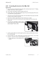
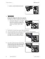
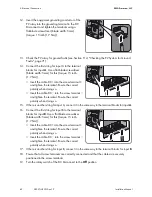
Page 37: ...breakers in the output circuit of the inverter and secure against reconnection 2 Ensure that no voltage is present between the AC cables to be connected 3 Remove all six screws of the lower enclosure lid using an Allen key AF 3 and remove the enclosure lid 4 Loosen the screw on the display and flip the display up until it clicks into place If present do not kink the adjacent Zigbee antenna cable 5...

Page 38: ...he equipment grounding conductor to the left when doing so 12 Secure the conical spring washer the grounding cable of the SPS module and the clamping bracket using the cheese head screw torque 53 in lbs 6 Nm The teeth of the conical spring washer must face the clamping bracket 8 Danger of crushing when safety levers snap shut The safety levers close by snapping down fast and hard Only press the sa...

Page 39: ...d the PV modules used must be suitable for use with this inverter The inverter has two input areas A and B The strings per input area must be designed identically Requirements for the PV Modules The limiting values for the maximum system voltage and the maximum short circuit current of the inverter must not be exceeded see Section 13 Technical Data page 77 The PV modules and strings connected to o...

Page 40: ...of delivery Conduit fittings 3 4 in 19 mm rain tight or for wet locations when installed outdoors Conduits 3 4 in 19 mm 6 4 3 Connecting the PV Array 1 Switch off or open all AC disconnecting switches and circuit breakers in the output circuit of the inverter and secure against reconnection 2 If an external DC disconnecting switch is available switch off or open the DC disconnecting switch 3 If th...

Page 41: ...he red cable into the RD screw terminal and tighten the terminal Insert the orange cable into the OR screw terminal and tighten the terminal Insert the black cable into the BK screw terminal and tighten the terminal 9 Install conduits with conduit fittings in the enclosure openings on the DC Disconnect 10 Feed the DC cables of the PV strings and the DC equipment grounding conductors through the co...

Page 42: ...able DC into the screw terminal and tighten the terminal Ensure the correct polarity when doing so 15 If there is another string for input A connect it in the same way to the terminal blocks for input A 16 Connect the first string for input B to the terminal blocks for input B Use a flat blade screwdriver blade width 5 mm for this torque 15 in lb 1 7 Nm Insert the cable DC into the screw terminal ...

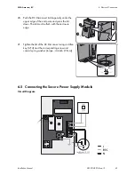
Page 43: ...er the upper edge of the enclosure and press the lid down The lid must be flush with the enclosure edge 21 Tighten the lid of the DC Disconnect using an Allen key AF 4 and the corresponding screw and conical spring washer torque 44 in lb 5 Nm 6 5 Connecting the Secure Power Supply Module Circuit Diagram Closing the DC Disconnect ...

Page 44: ...ents 5 insulated conductors for input switch output switch line conductor neutral conductor and equipment grounding conductor EGC must be available To avoid confusion the colors of the cables for switch and outlet should be different Solid or stranded wire of copper with no more than 19 single wires Conductor cross section 16 AWG to 12 AWG 1 3 mm to 3 3 mm The cables must be designed for the maxim...

Page 45: ...ound connection in the inverter 9 Secure the conduit fitting from the inside using the counter nut 10 Connect the insulated conductors that are connected to the three colored terminals of the SPS module to the outlet 7 Danger of fire due to short circuit A short circuit can occur in the secure power supply operation if the insulated conductors of the outlet and the switch have been swapped The sho...

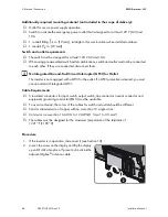
Page 46: ...gency power outlet 13 Label the switch using the supplied label Label the closed switch position with ON and the opened switch position with OFF 6 6 Connecting the Zigbee Antenna Screw the antenna into the screw connection on the inverter hand tight Information on the use of the outlet You will find further information on the use of the outlet and on the connection conditions in the user manual su...

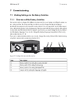
Page 47: ...in the supplementary sheet provided with the factory settings If the default country data set of the inverter does not apply to your country you must change the country data set and the display language You can also change the display language independent of the country data set see Section 7 1 3 If you use a communication product you can also change the country data set after commissioning using ...

Page 48: ... position Rotary switch B position Country data set Display language 0 0 Default settings Default settings 0 1 Retained English 0 2 Retained German 0 3 Retained French 0 4 Retained Spanish 0 5 Retained Italian 0 6 Retained Greek 0 7 Retained Czech 0 8 Retained Korean 0 9 Retained Portuguese 0 A Retained Dutch 0 B Retained Slovenian 0 C Retained Bulgarian 0 D Retained Polish 9 8 UL1741 English 9 9 ...

Page 49: ...see Section 7 2 The inverter will adopt the setting after commissioning This can take up to 5 minutes D 2 Island mode 60 Hz French D 3 Island mode 60 Hz Spanish D 4 Island mode 60 Hz Italian D 5 Island mode 60 Hz Greek D 6 Island mode 60 Hz Czech E 0 Island mode 50 Hz English E 1 Island mode 50 Hz German E 2 Island mode 50 Hz French E 3 Island mode 50 Hz Spanish E 4 Island mode 50 Hz Italian E 5 I...

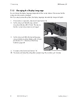
Page 50: ...tically changes to English 1 If the inverter is in operation disconnect it see Section 10 2 Set the rotary switch A to 0 using a slotted screwdriver blade width 2 5 mm This ensures that the country data set remains unchanged 3 Set the rotary switch B to the desired language using a slotted screwdriver blade width 2 5 mm see Section 7 1 1 Overview of the Rotary Switches page 47 4 Commission the inv...

Page 51: ...e rotary switch of the DC Disconnect to the On position The inverter carries out an arc fault circuit interrupter AFCI self test The green LED is lit and the display shows the device type the firmware version the device names the country data set and display language If communication is via Zigbee or Speedwire then the Zigbee status and the versions of the communication assemblies will also be dis...

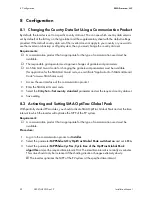
Page 52: ...ertificate Application for SMA Grid Guard Code at www SMA Solar com 1 Access the user interface of the communication product 2 Enter the SMA Grid Guard code 3 Select the CntrySet or Set country standard parameter and set the required country data set 4 Save setting 8 2 Activating and Setting SMA OptiTrac Global Peak With partially shaded PV modules you should activate SMA OptiTrac Global Peak and ...

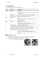
Page 53: ...lay messages of the start phase are repeated The following device properties will be displayed in succession Device type Firmware version Serial number or device name of the inverter For Zigbee communication version information of the assembly and status of the Zigbee communication The following status messages are possible SERVER COM data transmission active NET SEARCH searching for ZigBee networ...

Page 54: ...s glowing Data transmission active The inverter has set up a connection to a communication product and data transmission is active is flashing twice Searching for ZigBee network is flashing three times Network found but no reply from the gateway is flashing four times Gateway found but no connection to the server is flashing regularly No data transmission possible The inverter is trying to establi...

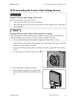
Page 55: ...splay switch off 5 Remove all six screws of the lower enclosure lid using an Allen key AF 3 and remove the enclosure lid Danger to life due to high voltages in the inverter Death or serious injury due to electric shock Only open the inverter in the order described here Before performing any tasks wait five minutes until the residual voltage has been drained from the components Damage to the seal o...

Page 56: ...test probe in each round opening of the terminal Ensure that no voltage is present between L1 and N Ensure that no voltage is present between L1 and the equipment grounding conductor Ensure that no voltage is present between L2 and N 6 Damage to the inverter due to electrostatic discharge The internal components of the inverter can be irreparably damaged by electrostatic discharge Ground yourself ...

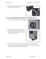
Page 57: ...n the rotary switch of the DC Disconnect to Off 2 Wait until the LEDs and inverter display switch off 3 Loosen the screw on the lower side of the DC Disconnect using an Allen key AF 4 and remove the lid of the DC Disconnect 4 If an external DC disconnecting switch is available open the DC disconnecting switch 5 If there is no external DC disconnecting switch available cover the PV modules with opa...

Page 58: ... a suitable measuring device Insert the test probe in each round opening of the terminal 6 Danger to life due to electric shock when touching the DC conductors and DC terminals High voltages are present in the DC cables and DC terminals Before performing any tasks wait five minutes until the residual voltage has been drained Do not touch the DC conductors and DC terminals ...

Page 59: ...t possible to change the grid parameters Parameters set successfully A new country data set has been configured SD card is read The inverter is currently reading the SD card Self test The self test is being carried out Set parameter The inverter is setting the parameters Standalone op The inverter is operating in the secure power supply operation Update completed The inverter has successfully comp...

Page 60: ...n the permissible range and this message is still displayed contact the SMA Service Line 202 to 205 Grid fault The utility grid has been disconnected the AC cable is damaged or the line voltage at the connection point of the inverter is too low The inverter has disconnected from the utility grid Corrective measures Ensure that the circuit breaker is switched on Ensure that the AC cable is not dama...

Page 61: ...he line voltage is permanently in the permissible range and this message is still displayed contact the SMA Service Line 401 to 404 Grid fault The inverter is no longer in grid parallel operation The inverter has stopped feeding into the utility grid Corrective measures Check the grid connection for strong short term frequency variations 501 Grid fault The power frequency is not within the permiss...

Page 62: ...sconnected from the utility grid Corrective measures If possible check the power frequency and observe how often fluctuations occur If there is a high number of fluctuations and this message is displayed frequently contact the grid operator and ask whether they approve a change of the operating parameters of the inverter If the grid operator approves discuss any changes to the operating parameters...

Page 63: ...easures Wait for higher irradiation If this event recurs at medium irradiation levels check the PV system design and the correct circuitry of the PV array 3401 to 3402 DC overvoltage Disconnect generator Overvoltage at the DC input The inverter may be destroyed When this message is signaled it is accompanied by rapid flashing of the backlight Corrective measures IMMEDIATELY DISCONNECT the inverter...

Page 64: ...nd faults see Section 11 4 3701 Resid curr too high Check generator The inverter has detected a residual current through brief PV array grounding Corrective measures Check the PV system for ground faults see Section 11 4 3801 to 3802 DC overcurrent Check generator The inverter switches off due to an overcurrent on the DC side Corrective measures If this event occurs frequently Check the design and...

Page 65: ... SMA Service Line Corrective measures Contact the SMA Service Line 6202 Self diagnosis Interference device The cause must be determined by the SMA Service Line Corrective measures Contact the SMA Service Line 6301 to 6314 Self diagnosis Interference device The cause must be determined by the SMA Service Line Corrective measures Contact the SMA Service Line 6401 to 6438 Self diagnosis Interference ...

Page 66: ... Inverter input B is defective Corrective measures Contact the SMA Service Line 7001 to 7002 Sensor fault A temperature sensor in the inverter is faulty The inverter interrupts the feed in operation Corrective measures Contact the SMA Service Line 7008 Disturbance sensor display temperature The ambient temperature sensor is faulty The display is not switched off at temperatures below 13 F 25 C and...

Page 67: ...e inverter continues feeding power into the grid Corrective measures Re format the SD card Re save the files to the SD card 7110 No update file found No new update file was found on the SD card The update failed The inverter continues feeding power into the grid Corrective measures Copy the update file into the SD card drive UPDATE directory 7201 to 7202 Data stor not poss Internal device fault th...

Page 68: ...r into the grid Corrective measures Re try update If this error occurs again contact the SMA Service Line 7326 Webconnect update unsuccessful Internal device fault the inverter continues feeding power into the grid Corrective measures Re try update If this error occurs again contact the SMA Service Line 7335 Zigbee update failed Internal device fault the inverter continues feeding power into the g...

Page 69: ...fficient ventilation 8101 to 8104 Comm disturbed The cause must be determined by the SMA Service Line Corrective measures Contact the SMA Service Line 8204 AFCI self test failed The cause must be determined by the SMA Service Line Corrective measures Contact the SMA Service Line 8206 Electr arc detected Please confirm by tapping The inverter has detected an electric arc and was recommissioned afte...

Page 70: ...measures If the display switched off due to the ambient temperature being too low wait until the ambient temperature is above 13 F 25 C If the ambient temperature is above 13 F 25 C contact the SMA Service Line 9002 Grid guard code invalid The SMA Grid Guard code entered is incorrect The parameters are still protected and cannot be changed Corrective measures Enter the correct SMA Grid Guard code ...

Page 71: ... configuration is not programmed The parameters to be changed are protected The DC voltage at the DC input is not sufficient to run the main CPU Corrective measures Check the settings of the rotary switches see Section 7 1 2 Changing the Country Data Set and the Display Language page 49 Enter the SMA Grid Guard code Ensure sufficient DC voltage green LED lights up or flashes Damage to the display ...

Page 72: ...ative terminals If the following results are returned simultaneously there is a ground fault in the PV system All measured voltages are stable The sum of the two voltages against the ground potential is approximately equal to the voltage between the positive and negative terminals 3 Determine the location of the ground fault via the ratio of the two measured voltages 4 Eliminate the ground fault 5...

Page 73: ...r new varistors directly from SMA for order numbers see Page 83 1 Disconnect the inverter and the DC Disconnect from voltage sources see Section 10 2 Insert the insertion tool into the contacts of the connecting terminal plate 3 Remove the varistor from the connecting terminal plate 4 Insert the new varistor into the terminal The labels of the varistor must face to the right at the inside of the i...

Page 74: ...acts of the connecting terminal plate 7 Push the DC Disconnect lid diagonally under the upper edge of the enclosure and press the lid down The lid must be flush with the enclosure edge 8 Tighten the lid of the DC Disconnect using an Allen key AF 4 and the corresponding screw and conical spring washer torque 44 in lb 5 Nm 9 Commission the inverter see Section 7 2 Closing the DC Disconnect ...

Page 75: ...ter to the DC Disconnect and pull it back into the inverter 8 Place the lower enclosure lid with the 6 screws on the enclosure and tighten them using an Allen key AF 3 in the order 1 to 6 torque 18 in lb 2 0 Nm 10 Loosen the screws of the DC Disconnect using an Allen key AF 4 and remove the DC Disconnect 12 Remove all DC cables from the DC Disconnect 9 Risk of burns due to hot enclosure parts Wait...

Page 76: ...e inverter Use the original packaging or packaging that is suitable for the weight and dimensions of the inverter see Section 13 Technical Data page 77 12 3 Disposing of the Inverter Dispose of the inverter in accordance with the locally applicable disposal regulations for electronic waste 16 Risk of injury when lifting the inverter or if it is dropped The inverter is heavy see Section 13 Technica...

Page 77: ...aximum short circuit current per MPP tracking input 19 A MPP tracking inputs 2 Strings per MPP tracking input 2 Rated power at 208 V or 240 V 60 Hz 3 000 W Maximum apparent power 3 050 VA Nominal AC voltage 208 V 240 V AC voltage range at 208 V nominal 183 V to 229 V AC voltage range at 240 V nominal 211 V to 264 V Nominal AC current at 208 V 14 5 A Nominal AC current at 240 V 12 5 A Maximum outpu...

Page 78: ... Maximum input current per MPP tracking input 15 A Maximum short circuit current per MPP tracking input 19 A MPP tracking inputs 2 Strings per MPP tracking input 2 Rated power at 208 V or 240 V 60 Hz 4 000 W Maximum apparent power 4 050 VA Nominal AC voltage 208 V 240 V AC voltage range at 208 V nominal 183 V to 229 V AC voltage range at 240 V nominal 211 V to 264 V Nominal AC current at 208 V 19 ...

Page 79: ...urrent per MPP tracking input 15 A Maximum short circuit current per MPP tracking input 19 A MPP tracking inputs 2 Strings per MPP tracking input 2 Rated power at 208 V 60 Hz 4 550 W Rated power at 240 V 60 Hz 5 000 W Maximum apparent power at 208 V 60 Hz 4 550 VA Maximum apparent power at 240 V 60 Hz 5 050 VA Nominal AC voltage 208 V 240 V AC voltage range at 208 V nominal 183 V to 229 V AC volta...

Page 80: ...nit Present DC arc fault circuit interrupter DC AFCI Width x height x depth inverter 195 16 in x 201 2 in x 75 16 in 490 mm x 519 mm x 185 mm Width x height x depth DC Disconnect 713 32 in x 1145 64 in x 71 2 in 187 mm x 297 mm x 190 mm Weight inverter 52 9 lb 24 kg Weight DC Disconnect 4 4 lb 2 kg Length x width x height of the inverter packaging 245 16 in x 231 2 in x 101 2 in 617 mm x 597 mm x ...

Page 81: ...th DIN EN 50178 1998 04 until 2013 replaced by DIN EN 62109 1 Electronics degree of protection NEMA 3R Protection class I Overvoltage category IV Approvals as at March 2013 UL 1741 UL 1699B IEEE 929 2000 IEEE 1547 Canadian Electrical Code CSA C22 2 N0 107 1 01 Grid configurations 208 120 V Wye 120 240 V Split phase Maximum rated switching current per string input 20 A Maximum switching voltage 600...

Page 82: ... Disconnect lid screw 44 in lbs 5 0 Nm Screws of the DC Disconnect retainer on the inverter wall mounting bracket 44 in lbs 5 0 Nm Screws of the DC Disconnect on the retainer 44 in lbs 5 0 Nm Ground connection in the inverter 53 in lbs 6 0 Nm Grounding screw in the grounding bracket of the DC Disconnect on the inverter 53 in lbs 6 0 Nm DC grounding terminal in the DC disconnect 15 in lbs 1 7 Nm DC...

Page 83: ... can be ordered from SMA or your distributor Description Brief description SMA order number DC replacement varistors Set with 4 varistors incl insertion tool SB VDC US02 Fan retrofit kit Retrofit kit for connecting a fan FANKIT02 10 RS485 module Module for communication via RS485 DM 485CB US 10 Speedwire module with Webconnect function Module for communication with Sunny Portal via Webconnect SWDM...

Page 84: ... If this equipment does cause harmful interference to radio or television reception which can be determined by turning the equipment off and on the user is encouraged to try to correct the interference by one or more of the following measures Reorient or relocate the receiving antenna Increase the separation between the equipment and the receiver Connect the equipment into an outlet on a circuit d...

Page 85: ...er if applicable Type and number of PV modules connected Mounting location and mounting altitude of the inverter Three digit or four digit event number and display message of the inverter Optional equipment e g communication products United States Estados Unidos SMA America LLC Rocklin CA 1 877 MY SMATech 1 877 697 6283 1 916 625 0870 toll free for USA Canada and Puerto Rico Llamada gratuita en EE...

Page 86: ......

Page 87: ......

Page 88: ...www SMA Solar com SMA Solar Technology SMA America LLC www SMA America com ...

Reviews: