Control Elements
SMA Solar Technology AG
82
SBU2200-TEN083320
Technical Description
9 Control Elements
Before commissioning the Sunny Backup System S, be sure to read the operating manual first.
The Sunny Backup 2200 is operated via the device display using the default settings only (the default
values are listed in section 20.2 „Adjustable System Parameters“ (142)).
To change the parameter settings of the Sunny Backup 2200, you need the Sunny Remote Control 1
(SRC-1).
9.1 Display of the Sunny Backup 2200
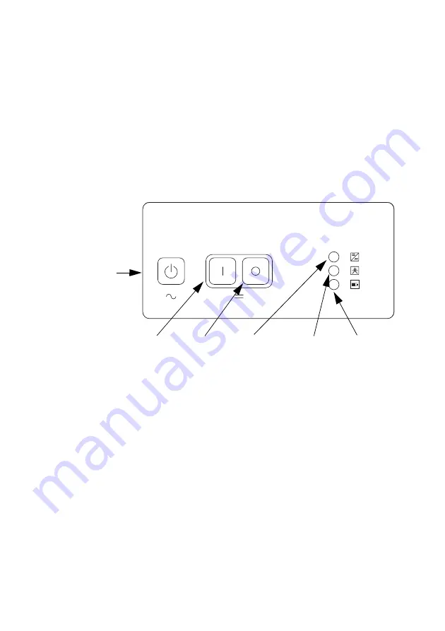
The figure below describes the control elements of the device display:
Explanation of the LEDs
In descending order, the three LEDs show the status messages for the
• inverter (Sunny Backup 2200)
• grid
• battery
The LEDs will glow green, red or yellow, or remain inactive, depending on the status message.
Start /
stop button
DC start
button
Inverter
LED
Battery
LED
Grid
LED
DC stop
button


