SMA Solar Technology America LLC
6 Electrical Connection
Installation Manual
CU1000-US-11-IA-en-13
29
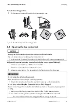
7. Insert one conduit fitting into each corresponding enclosure opening and tighten from within
using a conduit fitting locknut.
8. Attach the conduit to the conduit fitting.
9. Close any unused output opening on top of the Connection Unit with rain tight or wet location
hole seals or plugs.
10. The factory-mounted hole plugs provided with the Connection Unit can be used to seal any
unused input openings.
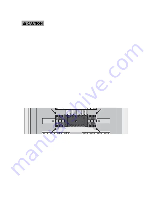
6.4 Connecting the Grounding Conductor
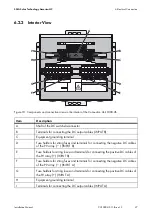
The Connection Unit is equipped with two terminals for connecting the grounding conductors. Each
terminal has two connection points.
Overview
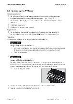
Figure 11: Terminals for connecting the grounding conductors
Cable requirements:
☐ The cable must be designed in accordance with the local installation requirements and for
temperatures of over +194°F (+90°C).
☐ Cable type: copper wire
☐ Use only solid or Class B or C stranded wire.
☐ Conductor cross-section: 12 to 1 AWG (single conductor), 12 to 4 AWG (two conductors)
Requirements:
☐ All conduits must be correctly connected to the Connection Unit (see Section 6.3).
☐ The DC switch-disconnector must be turned
OFF
and the lid of the Connection Unit must be
dismantled.
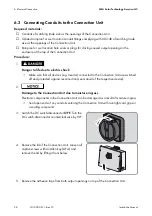
6.
Risk of injury when pressing out the filler plugs
• To connect the conduits to the input openings of the Connection Unit, gently press out one
filler plug for each conduit opening from the inside with a blunt object (e.g screwdriver
handle). Make sure not to damage components of the Connection Unit or the filler plugs.
Summary of Contents for CU 1000-US-11
Page 1: ...CU1000 US 11 IA en 13 Version 1 3 CA US Installation Manual SMA CONNECTION UNIT 1000 US...
Page 2: ......
Page 6: ...General Warnings SMA Solar Technology America LLC 6 CU1000 US 11 IA en 13 Installation Manual...
Page 44: ...www SMA Solar com SMA Solar Technology SMA Solar Technology America LLC www SMA America com...


