background image

SMA Solar Technology America LLC

1  Information on this Document

Installation Manual

CU1000-US-11-IA-en-13

9

1  Information on this Document

Validity

This document is valid for the following device types:

• CU 1000-US-11 (SMA Connection Unit 1000-US)

Target Group

This document is intended for qualified persons. Only qualified personnel with the appropriate skills 
are allowed to perform the tasks described in this document (see Section 2.2 "Skills of Qualified 
Persons", page 11).

Additional Information

Links to additional information can be found at www.SMA-Solar.com:

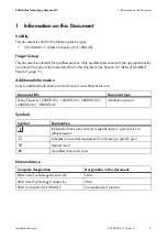
Symbols

Nomenclature

Document title

Document type

Sunny Tripower 12000TL-US / 15000TL-US / 20000TL-US / 
24000TL-US / 30000TL-US

Installation manual

Symbol

Explanation

Information that is important for a specific topic or goal, but is not 
safety-relevant

Indicates an essential requirement for achieving a specific goal

Desired result

A problem that could occur

Complete designation

Designation in this document

SMA Solar Technology America LLC

SMA

SMA Solar Technology Canada Inc.

SMA

SMA Connection Unit 1000-US

Connection Unit, product

Summary of Contents for CU 1000-US-11

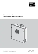
Page 1: ...CU1000 US 11 IA en 13 Version 1 3 CA US Installation Manual SMA CONNECTION UNIT 1000 US...

Page 2: ......

Page 3: ...ications are subject to change without notice Every attempt has been made to make this document complete accurate and up to date Readers are cautioned however that product improvements and field usage...

Page 4: ...could result in damage to or destruction of part or all of the SMA equipment and or other equipment connected to the SMA equipment or personal injury Warnings on this product The following symbols ar...

Page 5: ...ding without limitation applicable electrical safety codes All installations must conform with the laws regulations codes and standards applicable in the jurisdiction of installation SMA assumes no re...

Page 6: ...General Warnings SMA Solar Technology America LLC 6 CU1000 US 11 IA en 13 Installation Manual...

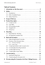
Page 7: ...16 4 5 String Fuses 17 5 Mounting 18 5 1 Requirements for Mounting 18 5 2 Mounting the Connection Unit 23 6 Electrical Connection 25 6 1 Safety during Electrical Connection 25 6 2 Overview of the Conn...

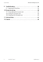
Page 8: ...11 IA en 13 Installation Manual 9 Troubleshooting 38 9 1 Replacing the String Fuses 38 10 Decommissioning 40 10 1 Disassembling the Connection Unit 40 10 2 Packing the Connection Unit 40 10 3 Disposin...

Page 9: ...Qualified Persons page 11 Additional Information Links to additional information can be found at www SMA Solar com Symbols Nomenclature Document title Document type Sunny Tripower 12000TL US 15000TL...

Page 10: ...se with the following transformerless SMA inverters STP 12000TL US 10 15000TL US 10 20000TL US 10 24000TL US 10 30000TL US 10 The installer is responsible for determining the appropriateness and safet...

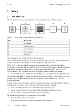
Page 11: ...st have the following skills Knowledge of how electrical devices and plants work and are operated Training in how to deal with the dangers and risks associated with installing and using electrical dev...

Page 12: ...Connection Unit e g inverter and protect against reconnection Cover the PV modules Turn the DC switch disconnector of the Connection Unit counterclockwise by 90 and set to OFF While in operation ensu...

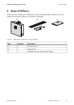
Page 13: ...k the scope of delivery for completeness and any externally visible damage Contact your distributor if the scope of delivery is incomplete or damaged Figure 2 Components included in the scope of deliv...

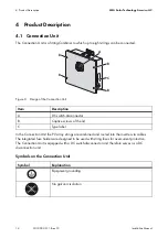
Page 14: ...it the PV array strings are combined and routed into the inverter via cables The integrated fuse holders are designed to be used with string fuses for overcurrent protection The Connection Unit is equ...

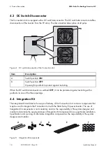
Page 15: ...due to high voltages The product operates at high voltages All work on the product must be carried out by qualified persons only Risk of burns from hot surfaces The product can get hot during operatio...

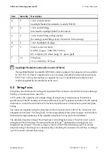
Page 16: ...4 Integration Kit The Integration Kit included in the scope of delivery of the Connection Unit contains components that may be used to integrate the Connection Unit with the SMA Sunny Tripower inverte...

Page 17: ...rating Isc of the PV module The National Electrical Code stipulates that all string fuses are designed to be at least 1 56 times as large as the Isc of the PV module being used The correct ampacity r...

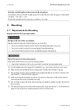
Page 18: ...document The ambient temperature must be within a permissible range see Section 11 Technical Data page 41 This will ensure optimal operation of the Connection Unit Example calculating the minimum siz...

Page 19: ...nology America LLC 5 Mounting Installation Manual CU1000 US 11 IA en 13 19 Dimensions for mounting Figure 6 Dimensions of the mounting points 466 mm 18 35 in 20 mm 0 79 in 407 mm 16 in 398 mm 15 67 in...

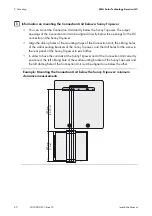
Page 20: ...the mounting straps of the Connection Unit the oblong holes of the wall mounting brackets of the Sunny Tripower and the drill holes for the screw in the rear panel of the Sunny Tripower to each other...

Page 21: ...a LLC 5 Mounting Installation Manual CU1000 US 11 IA en 13 21 Example Mounting the Connection Unit below the Sunny Tripower clearance measurements for use with Integration Kit conduits and fittings 40...

Page 22: ...mmended clearances Damage to the Connection Unit by mounting it in areas with a high snow accumulation Position the Connection Unit in such way that it will not be covered entirely with snow when moun...

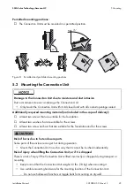
Page 23: ...to moisture and dust intrusion Dust or moisture intrusion can damage the Connection Unit Only mount the Connection Unit with its lid closed and with all conduit openings sealed Risk of burns due to ho...

Page 24: ...Connection Unit from the mounting location 5 Drill holes at the markings 6 Insert suitable screw anchors into the drill holes 7 Insert screws with washers through the oblong holes of the Connection U...

Page 25: ...e might be ice on the seal of the lid when there is frost or the temperatures are below freezing Remove it prior to opening the Connection Unit e g by melting the ice with warm air Adhere to the corre...

Page 26: ...ctrical Code CSA C22 1 Use only 194 F 90 C copper wire for all DC wiring connections to the screw terminals between the PV modules and the Connection Unit and between the Connection Unit and the inver...

Page 27: ...nal D Fuse holders for string fuses and terminals for connecting the negative DC cables of the PV array INPUT B E Fuse holders for string fuses and terminals for connecting the positive DC cables of t...

Page 28: ...sconnector OFF Turn the DC switch disconnector counterclockwise by 90 4 Remove the lid of the Connection Unit Loosen all captive screws with an Allen key AF 4 and remove the lid by lifting it from bel...

Page 29: ...ts Overview Figure 11 Terminals for connecting the grounding conductors Cable requirements The cable must be designed in accordance with the local installation requirements and for temperatures of ove...

Page 30: ...4 Connect the grounding conductor to one of the termination points of the ground terminal and tighten with a screwdriver torque at least 51 3 in lb 5 8 Nm 5 Ensure that the grounding conductor is sec...

Page 31: ...and the lid must be dismantled Procedure Connect the DC cables of the PV array to INPUT A and B as follows 3 Lead the DC cables of the PV array into the interior of the Connection Unit 4 Strip the ins...

Page 32: ...onally required material Cables for connecting the Connection Unit to the inverter If the DC switch disconnector should be protected against restarting a padlock can be used Cable requirements The DC...

Page 33: ...nverter 6 Tighten the screw terminals with a screwdriver torque 51 3 in lb 5 8 Nm 7 Mount the lid of the Connection Unit Position the lid in such a way that the protruding shaft in the Connection Unit...

Page 34: ...maximum allowable fuse rating is 20 A Procedure 2 Turn the DC switch disconnector OFF Turn the DC switch disconnector counterclockwise by 90 3 Remove the lid of the Connection Unit Loosen all captive...

Page 35: ...he Connection Unit Position the lid in such a way that the protruding shaft in the Connection Unit snaps into the provided opening of the DC switch disconnector Tighten all screws of the lid with an A...

Page 36: ...String fuses must be inserted in the Connection Unit Unused conduit openings of the Connection Unit must be sealed with rain tight or wet location hole seals or plugs Connection Unit must be connecte...

Page 37: ...lifting it from below 4 Open all fuse holders 6 Detach all DC cables from the terminals using a screwdriver 1 Danger to life due to electric shock Make sure that all devices e g inverter connected to...

Page 38: ...10 mm x 38 mm midget format The maximum allowable fuse rating is 20 A Procedure 2 Turn the DC switch disconnector OFF Turn the DC switch disconnector counterclockwise by 90 3 Remove the lid of the Co...

Page 39: ...holder 7 Close all safety levers all the way The safety levers audibly click into place 8 Mounting the lid of the Connection Unit Position the lid in such a way that the protruding shaft in the Connec...

Page 40: ...s 3 Mount the lid of the Connection Unit Position the lid in such a way that the protruding shaft in the Connection Unit snaps into the provided opening of the DC switch disconnector Attach all screws...

Page 41: ...strings 8 Strings for INPUT A 4 Strings for INPUT B 4 Maximum input voltage 1000 V CU 1000 US 11 Maximum number of outgoing strings 2 CU 1000 US 11 Overcurrent protection String fuses CU 1000 US 11 Fu...

Page 42: ...ackaging 22 11 64 in x 21 3 8 in 5 11 32 in 563 mm x 543 mm x 240 mm Transport weight 24 lb 11 kg Operating temperature range 40 F to 140 F 40 C to 60 C Storage temperature range 40 F to 140 F 40 C to...

Page 43: ...on Unit Type and number of the PV modules connected Mounting location and mounting height of the Connection Unit LED signal and error message of the inverter if applicable United States Estados Unidos...

Page 44: ...www SMA Solar com SMA Solar Technology SMA Solar Technology America LLC www SMA America com...

Reviews: