background image

8  Operation

SMA Solar Technology AG

Operating manual

EDMM-10-BE-en-20

37

8

Operation

8.1

Design of the User Interface

A

C

D

B

E

F

G

H

I

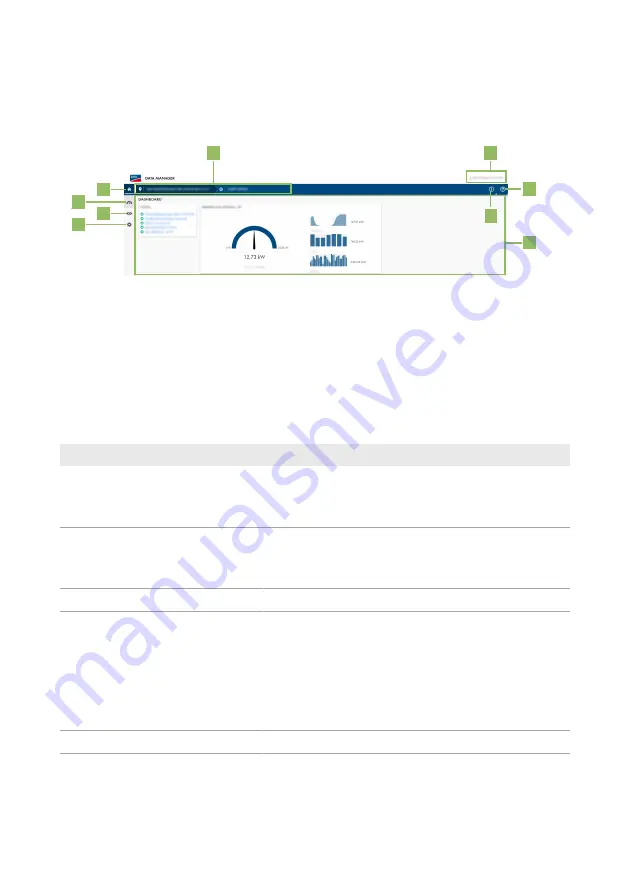
Figure 9: Design of the user interface (example)

The user interface of the product and the user interface of Sunny Portal are uniform. The product is
configured and commissioned on site via the user interface of the product.
The Sunny Portal serves as the user interface for the extended configuration of the product, of
system sections, systems, system groups and the entire system portfolio. The Sunny Portal monitors
and analyzes the system and its components on all levels.
The number of functions and menus depends on whether you are on the local user interface of the
product or in Sunny Portal.

Position

Designation

Description

A

Focus navigation

Enables the navigation between the following levels:

• System
• Device

B

User settings

Provides the following functions:

• Configuring personal data
• Log out

C

Help

Redirecting to help pages

D

System information

Displays the following information:

• System time
• IP address
• Firmware version
• Serial number
• Licenses

E

Content area

Displays the dashboard or content of the selected menu

Summary of Contents for DATA MANAGER M

Page 1: ...SUNNY BOY 10 30V DC X1 Digital Input RS485 ennexOS DATA MANAGER EDMM 10 BE en 20 Version 2 0 ENGLISH Operating manual SMA DATA MANAGER M with SUNNY PORTAL powered by ennexOS...

Page 2: ...tatutes and thus the above exclusion may not apply Specifications are subject to change without notice Every attempt has been made to make this document complete accurate and up to date Readers are ca...

Page 3: ...Supported Products 11 3 Scope of Delivery 13 4 Product Overview 14 4 1 Product Description 14 4 2 Symbols on the Product 15 4 3 Function Button 16 4 4 LED Signals 16 4 5 Sunny Portal 18 4 6 Interfaces...

Page 4: ...r Feed In 39 8 4 Configuring Reactive Power as a Function of Grid Voltage 41 8 5 Configuring Modbus Devices 42 8 6 Configuring a System with several Data Managers 43 8 7 Speedwire Encryption of the Sy...

Page 5: ...compliance with this document and all safety information 1 3 Content and Structure of this Document This document describes the mounting installation commissioning configuration operation troubleshoot...

Page 6: ...sages Terminals Elements on a user interface Elements to be selected Elements to be entered Connect the insulated conductors to the terminals X703 1 to X703 6 Enter 10 in the field Minutes Connects se...

Page 7: ...formation SMA Modbus Interface SMA DATA MANAGER M Technical Information PUBLIC CYBER SECURITY Guidelines for a Secure PV System Communication Technical information RS485 Cabling Plan Installation Manu...

Page 8: ...the operating license SMA Solar Technology AG shall not be held liable for any damage caused by such changes Any use of the product other than that described in the Intended Use section does not quali...

Page 9: ...n closer than 20 cm 8 in to the product for long periods of time NOTICE Damage to the product due to condensation If the product is moved from a cold environment to a warm environment condensation may...

Page 10: ...roduct to the utility grid contact your local grid operator The electrical connection of the product must be carried out by qualified persons only Ensure that the cables or conductors used for electri...

Page 11: ...nager with 1 Sunny Tripower Storage 60 1 SMA Inverter Manager with up to 42 Sunny Tripower 60 Sunny Highpower Peak1 Supported Products from Other Manufacturers Energy meters Power Analyser of the UMG...

Page 12: ...ual Irradiation sensors Anemometers Temperature sensors Signal receivers and digital and analog signal sources Signal sources with relay contacts Routers and network switches Routers and network switc...

Page 13: ...if the scope of delivery is incomplete or damaged Figure 1 Components included in the scope of delivery Position Quantity Designation A 1 SMA Data Manager M B 1 Two pole plug C 1 Six pole plug D 1 Six...

Page 14: ...onnecting to the network E Type label The type label clearly identifies the product You will require the information on the type label to use the product safely and when seeking customer sup port from...

Page 15: ...table for indoor installation CE marking The product complies with the requirements of the applicable EU directives RoHS RoHS labeling The product complies with the requirements of the applicable EU d...

Page 16: ...15 seconds resets password and administrator account of the Data Manager 15 to 20 seconds resets the Data Manager to the default settings Longer than 20 seconds no effect The length of time the funct...

Page 17: ...n has been pressed for less than 5 seconds Flashing orange and green in alter nation Glowing green Function button has been pressed for between 5 and 10 seconds Flashing orange and green in alter nati...

Page 18: ...em planning software from SMA 4 6 Interfaces and Functions The product can be equipped or retrofitted with the following interfaces and functions The availability of the functions depends on the produ...

Page 19: ...Ethernet TCP can be used for industrial use e g SCADA systems and for system communication with connected systems e g energy meters Via this Modbus interface data of the product can be queried and con...

Page 20: ...to the Sunny Portal and if necessary configured there SMA Smart Connected SMA Smart Connected is the free monitoring of the inverter via the SMA Sunny Portal Thanks to SMA Smart Connected the PV syste...

Page 21: ...trol can take place through direct parameter settings Q cos in the installation assistant or a variable specification from the grid operator via the Modbus interface or via analog signals The reactive...

Page 22: ...the specified conditions The mounting location must be suitable for the installation of the product The mounting location must be suitable for the weight and dimensions of the product see Section 11...

Page 23: ...There are two options for mounting the product Mounting on the top hat rail Mounting on a wall Mounting the Product on the DIN rail Additionally required mounting material not included in the scope of...

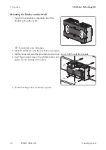
Page 24: ...oduct out from the inside The brackets snap into place 2 Mark the drill holes using the brackets as a template 3 Drill the holes and insert the provided screw anchors Do not drill through the brackets...

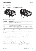
Page 25: ...Connection Cable Always proceed as follows to prepare each connection cable for connection to multipole plugs Procedure 1 Strip 40 mm 1 57 in of cable sheath from the end of the connection cable to w...

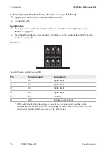
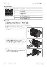
Page 26: ...be prepared for connection to the multipole terminal block see Section 6 2 page 25 Overview 6 6 1 1 5 5 3 3 4 4 2 2 Figure 6 Pin assignment for terminal X3 Pin Pin assignment Explanation 1 DI1 Digita...

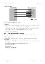
Page 27: ...ing a suitable tool and plug the conductors into these terminal positions 3 Connect the six pole plug to terminal X3 Observe the pin assignment 4 Note the terminal assignment 6 4 Connecting RS485 Devi...

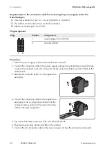
Page 28: ...length as the cable sheath 3 Shorten unused insulated conductors flush with the cable sheath 4 Strip off the conductor insulation by 6 mm 5 Release the conductor entries on the supplied six pole plug...

Page 29: ...r supply unit is close to the power supply unit The disconnection unit and the electrical outlet for the power supply unit must be freely accessible at all times NOTICE Damage to the product due to co...

Page 30: ...r manual 2 Connect the connection cable to the power supply unit see the manufacturer manual Make a note of the insulated conductor colors and trim the unused insulated conductors back to the cable sh...

Page 31: ...sent at the connection point of the utility grid Disconnect the connection point from voltage sources and ensure that the connection point is voltage free 9 Connect the other end of the AC connection...

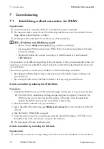
Page 32: ...s to connect your end device to the Data Manager via WLAN By entering the WLAN data located on the type label or the label included in delivery into your end device By scanning the QR code on the labe...

Page 33: ...serial number is part of the access addresses of the product Access address for Apple and Linux systems SMA serial number local e g SMA0123456789 local Access address for Windows and Android systems...

Page 34: ...n the web browser is used as system time If the difference between the time in the web browser and the system time is more than one minute the time is synchronized and the product restarted Configurin...

Page 35: ...ser in Sunny Portal or log into Sunny Portal as an existing user 3 Create a new system or add product to an existing system Register as a new user in Sunny Portal 1 Call up the Internet address https...

Page 36: ...required for user registration and the registration of your system in Sunny Portal Service access To ensure a better quality of service activate the switch for service access during registration Proc...

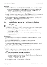
Page 37: ...system groups and the entire system portfolio The Sunny Portal monitors and analyzes the system and its components on all levels The number of functions and menus depends on whether you are on the loc...

Page 38: ...ated on each product via the user interface As administrator you can add further system users in Sunny Portal Thus users have access to their Sunny Portal system and local access via the user interfac...

Page 39: ...et Activating service access Configuring the SMA Smart Con nected Displaying status widget Creating and configuring system sec tions Displaying weather widget 8 3 Configuring Limitation of Active Powe...

Page 40: ...verters that support the fallback function In the event of a communication failure between the product and the inverter the inverter is reduced to an output power of 0 during fallback For more informa...

Page 41: ...d operator if necessary Enter correct values for system power Adjust the values for system power during system expansions Requirements There must be an appropriate energy meter installed at the grid c...

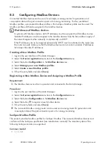
Page 42: ...Log into the user interface of the Data Manager 2 Select the Device registration menu item in the Configuration menu 3 Select the button Configuration in the Modbus devices row 4 Select Manage your o...

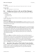
Page 43: ...en loop or closed loop control commands to the subordinate Data Manager via Modbus For this subordinate Data Managers must be integrated as Modbus devices into the system of the superordinate Data Man...

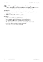
Page 44: ...in the local network must be in operation and connected to the product via an Internet router All devices must support the Speedwire encryption Procedure 1 Log into the user interface of the Data Mana...

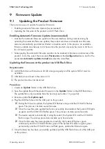
Page 45: ...aximum 32 GB storage capacity and file system FAT32 must be available USB flash drive at least in the version 2 0 The product must be commissioned Procedure 1 Create an Update folder on the USB flash...

Page 46: ...ameter Device updates turned on select the value Yes Updating the firmware at the Data Manager via USB flash drive Requirements A USB flash drive with maximum 32 GB storage capacity and file system FA...

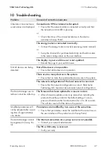
Page 47: ...in the system Ensure that no more than permissible devices are in the system The network configuration of the local network is incorrect Ensure that the network configuration is correct SMA Solar Tec...

Page 48: ...e Depending on the time of day the weather and the condition of the PV modules e g affected by pollution or covered with snow the DC input voltage may be too low for a firmware update Ensure that ther...

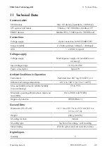
Page 49: ...as an accessory Input voltage range 10 V to 30 V DC Power consumption Type 4 W Ambient Conditions in Operation Environment Restricted class 3K7 reg IEC60721 3 3 Ambient and storage temperature 20 C t...

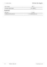
Page 50: ...Technical Data SMA Solar Technology AG Operating manual EDMM 10 BE en 20 50 Input voltage 24 VDC Maximum cable length 30 m 98 ft Equipment Warranty 2 years Certificates and approvals www SMA Solar co...

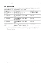
Page 51: ...y unit for SMA Data Manager M CLCON PWRSUPPLY ioLogik E1241 I O system by Moxa Europe GmbH 4AO eIO E1241 ioLogik E1242 I O system by Moxa Europe GmbH 4AI 4DI 4DIO eIO E1242 ioLogik E1260 I O system by...

Page 52: ...nline Service Center www SMA Service com Belgien Belgique Belgi Luxemburg Luxembourg Nederland SMA Benelux BVBA SPRL Mechelen 32 15 286 730 for Netherlands 31 30 2492 000 SMA Online Service Center www...

Page 53: ...Thonglor 17 Klongton Nua Wattana 10110 Bangkok Thailand 66 20598220 smaservice spe co th Service Partner for Utility Tirathai E S Co Ltd 516 1 Moo 4 Bangpoo Indus trial Estate Sukhumvit Road T Praksa...

Page 54: ...Rocklin CA Toll free for USA and US Territories 1 877 MY SMATech 1 877 697 6283 International 1 916 625 0870 Canada SMA Solar Technology Canada Inc Mississauga Toll free for Canada Sans frais pour le...

Page 55: ...57 374 LVD Radio Equipment Directive 2014 53 EU 22 5 2014 L 153 62 RED Restriction of the use of certain hazardous substances 2011 65 EU L 174 88 June 8 2011 and 2015 863 EU L 137 10 March 31 2015 RoH...

Page 56: ...frequency energy and if not installed and used in accordance with the instructions may cause harmful interference to radio communications However there is no guarantee that interference will not occur...

Page 57: ......

Page 58: ...www SMA Solar com...

Reviews: