background image

DC-CMB-IA-U15-xx |  910.400.190A   |   Version 10.0

ENGLISH

  FRANÇAIS  

Installation Manual - Installationshandbuch  - Manuel d’Installation

SMA STRING-COMBINER  
DC-CMB-U15-16 / DC-CMB-U15-24 / DC-CMB-U15-32 

DEUTSCH

Summary of Contents for DC-CMB-U15-10

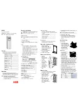
Page 1: ...DC CMB IA U15 xx 910 400 190A Version 10 0 ENGLISH FRAN AIS Installation Manual Installationshandbuch Manuel d Installation SMA STRING COMBINER DC CMB U15 16 DC CMB U15 24 DC CMB U15 32 DEUTSCH...

Page 2: ...not explicitly identified as such A lack of identification does not mean that a product or symbol is not trademarked The BLUETOOTH word mark and logos are registered trademarks owned by Bluetooth SIG...

Page 3: ...a DC CMB U15 16 20 6 3 3 Inserting the Cables into the Switch Cabinet DC CMB U15 24 21 6 3 4 Overview of the Connection Area DC CMB U15 24 22 6 3 5 Inserting the Cables into the Switch Cabinet DC CMB...

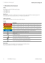
Page 4: ...icates a hazardous situation which if not avoided will result in death or serious injury Indicates a hazardous situation which if not avoided can result in death or serious injury Indicates a hazardou...

Page 5: ...clarifications or additional information contact the SMA technical service Symbol Explanation Once the product has been removed from its original packaging visually inspect for damage that may have o...

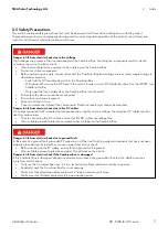
Page 6: ...and protected from exposure to direct sunlight These measures are important for preventing unnecessary and excessive overheating which prolonged in time impairs the duration and operation of parts ins...

Page 7: ...round and short circuit Cover or isolate any adjacent live components Protective covers must always be mounted Danger to life from electric shock due to live DC cables DC cables connected to PV module...

Page 8: ...that the contact resistances increase This can cause components to overheat and catch fire Ensure that live bolted connections are always tightened with the exact torque specified in this document Whe...

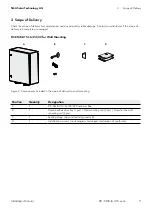
Page 9: ...y is incomplete or damaged DC CMB U15 16 24 32 for Wall Mounting A B C D Figure 2 Components included in the scope of delivery for wall mounting Position Quantity Designation A 1 DC CMB U15 16 24 32 C...

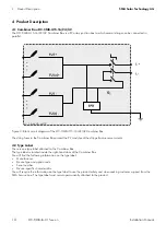
Page 10: ...r Box protect the PV modules of the strings from reverse currents 4 2 Type Label There is one type label attached to the Combiner Box The type label is located inside the right hand door of the Combin...

Page 11: ...ied with the product CE marking The product complies with the requirements of the applicable EU directives WEEE designation Do not dispose of the product together with the household waste but in accor...

Page 12: ...the reverse current the more the PV modules of the faulty string will heat up Strong heat build up can destroy the modules of the faulty string A reverse current can be caused by the following a short...

Page 13: ...ape routes o The mounting location must be freely and safely accessible at all times without the necessity for any auxiliary equipment such as scaffolding or lifting platforms Non fulfillment of these...

Page 14: ...onnections due to improper transport and installation The cable glands and plug connections protrude from the enclosure When transporting and mounting the Combiner Box ensure that the cable glands and...

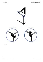
Page 15: ...rk the position of the drill holes on the wall or stand 2 Drill holes at the marked positions 3 If necessary insert the screw anchors Attach the two mounting rails to the Combiner Box with the screws...

Page 16: ...16 Installation Manual SMA Solar Technology AG DC CMB IA U15 xx en 5 Assembly B A Horizontal mounting Vertical mounting B A Figure 6c...

Page 17: ...IA U15 xx en 5 Assembly 5 2 Drilling Template for Mounting Figure 7 Dimension Dimension mm A B C D E F G H K L M MODELS DC CMB U15 16 DC CMB U15 24 498 550 575 599 650 675 299 5 337 5 287 5 249 8 DC...

Page 18: ...to end with suitable tips in order to prevent possible short circuits between adjacent cables Note that the panel does not contain blocking diodes If the photovoltaic array has zones that are not irr...

Page 19: ...remove the DC fuses in the central inverter or main DC distribution box Use an LV HRC fuse handle Only open the fuse holders when the Combiner Box is switched off Ensure that the device cannot be reco...

Page 20: ...dependent on the order option The maximum configuration of the Combiner Box is shown in the overview diagrams Combiner Box with cable glands for the string cables Figure 9 Connections as exemplified...

Page 21: ...into the Switch Cabinet DC CMB U15 24 Figure 10 Bottom view of Combiner Box with cable glands example Position Designation A Cable entry for connecting the strings positive terminal B Output DC cable...

Page 22: ...dependent on the order option The maximum configuration of the Combiner Box is shown in the overview diagrams Combiner Box with cable glands for the string cables Figure 11 Connections as exemplified...

Page 23: ...into the Switch Cabinet DC CMB U15 32 Figure 12 Bottom view of Combiner Box with cable glands example Position Designation A Cable entry for connecting the strings positive terminal B Output DC cable...

Page 24: ...dependent on the order option The maximum configuration of the Combiner Box is shown in the overview diagrams Combiner Box with cable glands for the string cables Figure 13 Connections as exemplified...

Page 25: ...rough unsealed cable glands 6 5 1 Cable requirements o PV cable type must be available o Conductor cross section of the string cable for connection of one string cable to the fuse holders 4 mm2 to 6 m...

Page 26: ...ssembly of the Connection 6 7 1 Two Terminal Lugs Figure 14 Position Designation A Screw M12x35 B Washer C Copper busbar D Spring washer E Nut M12 F Terminal lug 6 7 2 One Terminal Lug Figure 15 Posit...

Page 27: ...ial not included in the scope of delivery o Ring terminal lugs size for M12 screw o Clean cloth o Ethanol cleaning agent Procedure 1 Strip off the DC cable insulation 2 Fit the DC main cables with rin...

Page 28: ...ted 7 2 Commissioning the Combiner Box 7 2 1 Requirements for Commissioning Commissioning must be performed by Service employees only Commissioning of the Combiner Box must be performed by Service emp...

Page 29: ...ests have generated positive results Proceed with the start up operations of the system Immediately correct the wiring if one of the aforesaid conditions is not valid because continuation of this situ...

Page 30: ...s on the terminals Yearly Visual inspection The door panel of the enclosure is firmly closed at the end of all the checks and after any maintenance Yearly Visual inspection 8 2 Extraordinary Maintenan...

Page 31: ...isolate any adjacent live components Risk of burns from touching hot components Wear personal safety equipment when working on the device Procedure 1 Switch off the DC load break switch This ensures t...

Page 32: ...1 Open the doors of the Combiner Box 2 Disconnect the string cables from the fuse holders 3 Disconnect the DC main cable 4 Disconnect the grounding cable 5 Release the cable glands 6 Pull all cables o...

Page 33: ...NPUT DATA Number of strings 16 24 32 Sealing range cable entry 5 mm to 8 mm Input cable glands entry per pole 4 PG32 with 4 input each 6 PG32 with 4 input each 8 PG32 with 4 input each Input connectio...

Page 34: ...chland Tyskland Deutschland SMA Solar Technology AG Niestetal Medium Power Solutions Wechselrichter Kommunikation SMA Online Service Center 49 561 9522 1499 49 561 9522 2499 www SMA de Service Hybrid...

Page 35: ...ezi esko Cehia Schweiz Siehe Deutschland Slovensko pozri esko esk republika South Africa SMA Solar Technology South Africa Pty Ltd Centurion Pretoria 08600 SUNNY 08600 78669 International 27 12 643 17...

Page 36: ......

Page 37: ...Installationshandbuch SMA STRING COMBINER DC CMB U15 16 DC CMB U15 24 DC CMB U15 32 DC CMB IA U15 xx de 910 400 190DE Version 10 0 DEUTSCH...

Page 38: ...klich als solche gekennzeichnet werden Die fehlende Kennzeichnung bedeutet nicht dass ein Produkt oder Symbol nicht gesch tzt ist Die BLUETOOTH Wortmarke und Logos sind eingetragene Warenzeichen der B...

Page 39: ...6 19 6 3 2 bersicht ber den Anschlussbereich DC CMB U15 16 20 6 3 3 Einf hrung der Kabel in den Schaltschrank DC CMB U15 24 21 6 3 4 bersicht ber den Anschlussbereich DC CMB U15 24 22 6 3 5 Einf hrung...

Page 40: ...die zum Tod oder zu schweren Verletzungen f hrt wenn sie nicht vermieden wird Hinweis auf eine Gefahrensituation die zum Tod oder zu schweren Verletzungen f hren kann wenn sie nicht vermieden wird Hi...

Page 41: ...nd Gebrauch der Combiner Box durchgelesen und genau verstanden werden Wenden Sie sich bitte an den technischen Kundendienst von SMA f r n here Informationen und Erl uterungen Symbole Bedeutung Unterzi...

Page 42: ...m ige Luftzirkulation sicherstellen Bei Au eninstallationen in einem st ndig beschatteten Bereich positionieren und vor direkter Sonneneinstrahlung sch tzen Diese Ma nahmen sind wichtig um eine unn ti...

Page 43: ...lie en Alle angrenzenden spannungsf hrenden Komponenten isolieren oder abdecken Schutzabdeckung m ssen immer montiert sein Lebensgefahr durch Elektroschock aufgrund spannungsf hrender DC Kabel An Sonn...

Page 44: ...chraubverbindungen sodass die Kontaktwiderst nde steigen Dadurch k nnen sich die Komponenten berhitzen und entz nden Ziehen Sie spannungsf hrende Schraubverbindungen immer genau mit dem in diesem Hand...

Page 45: ...umfang unvollst ndig ist oder Sch den aufweist DC CMB U15 16 24 32 f r Wandmontage A B C D Abbildung 2 Komponenten des Lieferumfangs f r Wandmontage Position Quantity Designation A 1 DC CMB U15 16 24...

Page 46: ...rangsicherungen in der Combiner Box sch tzen die PV Module der Str nge vor R ckstrom 4 2 Typenschild An der Combiner Box ist ein Typenschild angebracht Das Typenschild befindet sich an der Innenseite...

Page 47: ...des Produkts beachten CE Kennzeichnung Das Produkt erf llt die Anforderungen der geltenden EU Richtlinien WEEE Kennzeichnung Produkt nicht im unsortierten Siedlungsabfall entsorgen sondern entspreche...

Page 48: ...rom desto mehr erhitzen sich die PV Module des fehlerhaften Strangs Starke berhitzung kann die Module des fehlerhaften Strangs zerst ren R ckstrom kann folgende Ursachen haben Kurzschluss in einem ode...

Page 49: ...ren o Der Montageort muss jederzeit frei und sicher ohne die Notwendigkeit von Hilfsmitteln z B Ger ste oder Hebeb hnen zug nglich sein Die Nichterf llung dieser Kriterien kann Wartungsarbeiten beschr...

Page 50: ...Steckverbindungen durch Transport und Installationsfehler Die Kabelverschraubungen und Steckverbindungen ragen ber das Geh use heraus Stellen Sie bei Transport und Montage der Combiner Box sicher dass...

Page 51: ...and oder am St nder 2 F hren Sie die Bohrungen an den markierten Stellen aus 3 Setzen Sie bei Bedarf die Ankerschrauben ein Befestigen Sie die beiden Montageschienen mit den mitgelieferten Schrauben a...

Page 52: ...16 Manuel d Installation SMA Solar Technology AG DC CMB IA U15 xx de 5 Montage B A Horizontalmontage Vertikalmontage B A Abbildung 6c...

Page 53: ...A U15 xx de 5 Montage 5 2 Bohrschablone f r die Montage Abbildung 7 Abmessungen Abmessungen mm A B C D E F G H K L M MODELLE DC CMB U15 16 DC CMB U15 24 498 550 575 599 650 675 299 5 337 5 287 5 249 8...

Page 54: ...beneinander liegenden Kabeln zu vermeiden Bitte beachten Sie dass die Platte keine Sperrdioden enth lt Wenn bestimmte Zonen in der Photovoltaikanlage nicht gleichm ig bestrahlt werden z B weil diese t...

Page 55: ...oder im DC Hauptverteilerkasten Benutzen Sie einen LV HRC Sicherungshebel ffnen Sie den Sicherungshalter nur wenn die Combiner Box ausgeschaltet ist Stellen Sie sicher dass das Ger t nicht wieder ange...

Page 56: ...Bestelloptionen ab In den bersichtsdiagrammen wird die maximale Konfiguration der Combiner Box angezeigt Combiner Box mit Kabelverschraubungen f r die Kabel der Str nge Abbildung 9 Anschl sse wie im...

Page 57: ...tschrank DC CMB U15 24 Abbildung 10 Ansicht der Combiner Box mit Kabelverschraubungen von unten Beispiel Position Bezeichnung A Kabeleinf hrung zum Anschluss der Str nge Positivklemme B Ausgang DC Kab...

Page 58: ...Bestelloptionen ab In den bersichtsdiagrammen wird die maximale Konfiguration der Combiner Box angezeigt Combiner Box mit Kabelverschraubungen f r die Kabel der Str nge Abbildung 11 Anschl sse wie im...

Page 59: ...tschrank DC CMB U15 32 Abbildung 12 Ansicht der Combiner Box mit Kabelverschraubungen von unten Beispiel Position Bezeichnung A Kabeleinf hrung zum Anschluss der Str nge Positivklemme B Ausgang DC Kab...

Page 60: ...Bestelloptionen ab In den bersichtsdiagrammen wird die maximale Konfiguration der Combiner Box angezeigt Combiner Box mit Kabelverschraubungen f r die Kabel der Str nge Abbildung 13 Anschl sse wie im...

Page 61: ...durch unversiegelte Dichtungsstutzen im Combiner Box durchdringen 6 5 1 Kabelanforderungen o PV Kabel erforderlich o Leiterquerschnitt des Strangkabels f r den Anschluss eines Strangkabels an die Sic...

Page 62: ...lussmontage 6 7 1 Zwei Kabelschuhe Abbildung 14 Position Bezeichnung A Schraube M12x35 B Scheiben C Kupferschienen D Federringe E Mutter M12 F Anschlu fahnen 6 7 2 Eine Kabelschuhe Abbildung15 Positio...

Page 63: ...aufweisen Zus tzlich erforderliches Material nicht im Lieferumfang enthalten o Ringkabelschuhe Gr e f r M12 Schrauben o Reinigungstuch o Ethanolreinigungsmittel Montageanleitung 1 Entfernen Sie die D...

Page 64: ...hutzabdeckung m ssen immer montiert sein 7 2 Inbetriebnahme der Combiner Box 7 2 1 Anforderungen f r die Inbetriebnahme Die Inbetriebnahme darf nur vom Kundendienstpersonal durchgef hrt werden Die Inb...

Page 65: ...n Tests erfolgreich abgeschlossen wurden Lassen Sie die Anlage anlaufen Korrigieren Sie sofort die Verkabelung wenn die oben genannten Bedingungen nicht gegeben sind da die Fortsetzung des Betriebs un...

Page 66: ...erbrennung an den Klemmen J hrlich Sichtpr fung Die Geh uset r ist am Ende aller Kontrollen und Wartungsarbeiten fest verschlossen J hrlich Sichtpr fung 8 2 Au erordentliche Wartung Benutzen Sie nur m...

Page 67: ...ie en Verbrennungsgefahr durch Ber hrung hei er Komponenten Tragen Sie bei der Arbeit am Ger t Box pers nliche Schutzausr stung Anleitung 1 DC Lasttrennschalter ausschalten Dadurch wird sichergestellt...

Page 68: ...werden Anleitung 1 T ren der Combiner Box ffnen 2 Die Strangkabel von den Sicherungshaltern trennen 3 DC Hauptkabel trennen 4 Erdungskabel trennen 5 Kabelverschraubungen l sen 6 Alle Kabel aus den Kab...

Page 69: ...Dichtbereich der Kabeleinf hrung 5 mm bis 8 mm Eingangskabelverschraubungen pro Pol 4 PG32 mit 4 Eing ngen jeweils 6 PG32 mit 4 Eing ngen jeweils 8 PG32 mit 4 Eing ngen jeweils Eingangsanschluss Direk...

Page 70: ...schland SMA Solar Technology AG Niestetal Medium Power Solutions Wechselrichter Kommunikation SMA Online Service Center 49 561 9522 1499 49 561 9522 2499 www SMA de Service Hybrid Energy Solutions Sun...

Page 71: ...chweiz Siehe Deutschland Slovensko pozri esko esk republika South Africa SMA Solar Technology South Africa Pty Ltd Centurion Pretoria 08600 SUNNY 08600 78669 International 27 12 643 1785 United Kingdo...

Page 72: ......

Page 73: ...Manuel d Installation COFFRET DE REGROUPEMENT DES CHA NES SMA DC CMB U15 16 DC CMB U15 24 DC CMB U15 32 DC CMB IA U15 xx fr 910 400 190FR Version 10 0 FRAN AIS...

Page 74: ...elles ne sont pas explicitement identifi es comme telles Un manque d identification ne signifie pas qu un produit ou un symbole n est pas d pos La marque et les logos BLUETOOTH sont des marques d pos...

Page 75: ...e de la Zone de Connexion DC CMB U15 16 20 6 3 3 Ins rer les C bles dans l Armoire lectrique DC CMB U15 24 21 6 3 4 Vue d ensemble de la Zone de Connexion DC CMB U15 24 22 6 3 5 Ins rer les C bles dan...

Page 76: ...ereuse qui si elle n est pas vit e entra nera la mort ou des blessures graves Indique une situation dangereuse qui si elle n est pas vit e peut entra ner la mort ou des blessures graves Indique une si...

Page 77: ...trique Par cons quent les consignes de s curit suivantes doivent tre lues et comprises avant d installer et d utiliser le Coffret de Regroupement Pour tout claircissement ou information suppl mentaire...

Page 78: ...os assurez vous que la zone est ventil e et permet une recirculation de l air r guli re En cas d installation dans un environnement ouvert placez le bo tier dans une zone constamment ombrag e et prot...

Page 79: ...t circuitez Couvrez ou isolez tout composant voisin sous tension Des protections doivent toujours tre mont es Danger de mort d un choc lectrique d des c bles CC sous tension Les c bles CC branch s des...

Page 80: ...augmentent Cela peut entra ner la surchauffe des composants qui peuvent s enflammer Assurez vous que les assemblages boulonn s sont toujours serr s avec le couple exact sp cifi dans ce document Lorsq...

Page 81: ...u endommag DC CMB U15 16 24 32 pour Fixation Murale A B C D Figure 2 Composants inclus dans la livraison pour fixation murale Position Quantity Designation A 1 DC CMB U15 16 24 32 Combiner Box B 1 cl...

Page 82: ...gent les modules PV des cha nes de courants inverses 4 2 Plaque Signal tique Il y a une plaque signal tique accompagnant le Coffret de Regroupement La plaque signal tique est situ e l int rieur de la...

Page 83: ...es dans le manuel fourni avec le produit Marquage CE Le produit est conforme aux exigences des directives europ ennes en vigueur D nomination DEEE Ne pas liminer le produit avec les d chets domestique...

Page 84: ...le courant inverse est lev plus les modules PV de la cha ne d fectueuse se r chaufferont Une forte accumulation de chaleur peut d truire les modules de la cha ne d fectueuse Un courant inverse peut a...

Page 85: ...doit pas bloquer d issue de secours o L emplacement de montage doit tre accessible librement et en s curit en tout temps sans la n cessit d quipements auxiliaires comme un chafaudage ou une plate form...

Page 86: ...s de raccordement dus un transport et une installation incorrects Les presse toupes et les fiches de raccordement d passent du bo tier Lors du transport et du montage du Coffret de Regroupement assure...

Page 87: ...n des trous de per age sur le mur ou le support 2 Percez les trous aux emplacements indiqu s 3 Si n cessaire ins rez les chevilles Fixez les deux rails de montage au Coffret de Regroupement avec les v...

Page 88: ...16 Manuel d Installation SMA Solar Technology AG DC CMB IA U15 xx fr 5 Assemblage B A Montage horizontal Montage vertical B A Figure 6c...

Page 89: ...U15 xx fr 5 Assemblage 5 2 Gabarit de Per age pour le Montage Figure 7 Dimensions Dimension mm A B C D E F G H K L M MOD LES DC CMB U15 16 DC CMB U15 24 498 550 575 599 650 675 299 5 337 5 287 5 249...

Page 90: ...des c bles voisins Remarquez que le panneau ne contient pas de diodes de blocage Si le groupe photovolta que a des zones qui ne sont pas ensoleill es de mani re gale par exemple cause d un ombrage par...

Page 91: ...l onduleur central ou la bo te de distribution CC principale Utilisez une poign e pour fusibles BT HPC Ouvrez les porte fusibles seulement quand le Coffret de Regroupement est teint Assurez vous que...

Page 92: ...iguration maximale du Coffret de Regroupement est indiqu e dans les sch mas d ensemble Coffret de Regroupement avec presse toupes pour les c bles des cha nes Figure 9 Branchements comme indiqu s dans...

Page 93: ...C CMB U15 24 Figure 10 Vue de dessous du Coffret de Regroupement avec les presse toupes exemple Position Designation A Entr e de c ble pour le branchement des cha nes borne positive B Presse toupe CC...

Page 94: ...iguration maximale du Coffret de Regroupement est indiqu e dans les sch mas d ensemble Coffret de Regroupement avec presse toupes pour les c bles des cha nes Figure 11 Branchements comme indiqu s dans...

Page 95: ...C CMB U15 32 Figure 12 Vue de dessous du Coffret de Regroupement avec les presse toupes exemple Position Designation A Entr e de c ble pour le branchement des cha nes borne positive B Presse toupe CC...

Page 96: ...iguration maximale du Coffret de Regroupement est indiqu e dans les sch mas d ensemble Coffret de Regroupement avec presse toupes pour les c bles des cha nes Figure 13 Branchements comme indiqu s dans...

Page 97: ...o Des c bles de type PV doivent tre disponibles o Section du conducteur du c ble de la cha ne pour le branchement d un c ble de la cha ne aux porte fusibles 4 mm2 6 mm2 Proc dure 1 Fixez les c bles d...

Page 98: ...age du Branchement 6 7 1 Deux Cosses Bornes Figure 14 Position Designation A Vis M12x35 B Rondelle C Barre de cuivre D Rondelle lastique E crou M12 F Cosse borne 6 7 2 Une Cosse Borne Figure 15 Positi...

Page 99: ...es anneau taille pour vis M12 o Chiffon propre o Nettoyant base d thanol Proc dure 1 Enlevez l isolation du c ble CC 2 Ins rez les cosses bornes anneau sur les c bles CC principaux 3 Nettoyez les surf...

Page 100: ...out composant voisin sous tension Des protections doivent toujours tre mont es 7 2 Mise en Service du Combiner Box 7 2 1 Exigences pour la Mise en Service La mise en service doit tre effectu e uniquem...

Page 101: ...les ont eu des r sultats positifs Proc dez aux op rations de d marrage du syst me Corrigez imm diatement le c blage si une des conditions mentionn es est invalide car si cette situation se prolonge el...

Page 102: ...rnes Annuellement Inspection visuelle Le panneau de la porte du bo tier est bien ferm la fin de toutes les v rifications et de tout entretien Annuellement Inspection visuelle 8 2 Entretien Extraordina...

Page 103: ...chant les composants chauds Portez des quipements de protection individuels lorsque vous travaillez sur le dispositif Proc dure 1 teignez le disjoncteur coupure de charge CC Cela assure qu il n y a pa...

Page 104: ...rtes du Coffret de Regroupement 2 D branchez les c bles de cha ne des porte fusibles 3 D branchez le c ble CC principal 4 D branchez le c ble de mise la terre 5 Desserrez les presse toupes 6 Retirez t...

Page 105: ...re de cha nes 16 24 32 Plage de serrage de l entr e du c ble 5 mm 8 mm Entr es par presse toupe par p le 4 PG32 avec 4 entr es chacun 6 PG32 avec 4 entr es chacun 8 PG32 avec 4 entr es chacun Prise d...

Page 106: ...utschland Tyskland Deutschland SMA Solar Technology AG Niestetal Medium Power Solutions Wechselrichter Kommunikation SMA Online Service Center 49 561 9522 1499 49 561 9522 2499 www SMA de Service Hybr...

Page 107: ...chweiz Siehe Deutschland Slovensko pozri esko esk republika South Africa SMA Solar Technology South Africa Pty Ltd Centurion Pretoria 08600 SUNNY 08600 78669 International 27 12 643 1785 United Kingdo...

Page 108: ...SMA Solar Technology www SMA Solar com...

Reviews: