
DC-CMB-IA-U15-xx-en
33
Installation Manual
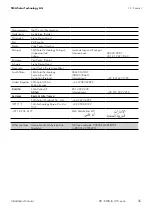
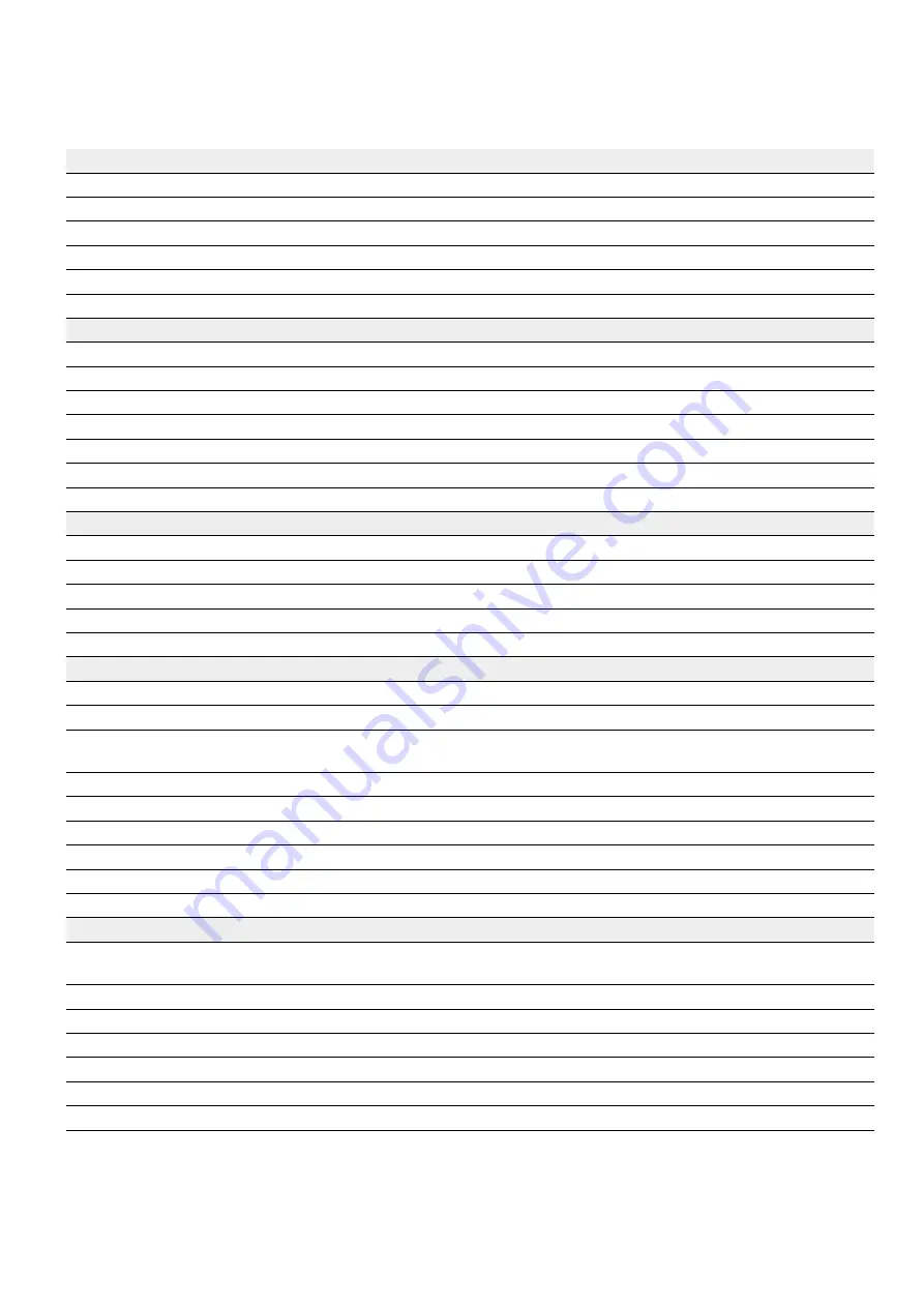
11 Technical Data
SMA Solar Technology AG
GENERAL DATA
DC-CMB-U15-16
DC-CMB-U15-24
DC-CMB-U15-32
Max. voltage (V
N
)
1,500 V
DC
(Note 1)
Max. input short-circuit current (IscSTC)
17.2 A
13.75 A
10.31 A
Max. output short-circuit current (IscSTC)
275 A
330 A
330 A
Max Number Switch opening under load
1,000
1,000
1,000
MECHANICAL DATA
Enclosure
GRP (Glass Fiber Reinforced Polyester)
Enclosure Dimensions (W x D x H in mm)
550 x 270 x 650
618 x 325 x 822
Weight
25 kg
28 kg
40 kg
Degree of Protection
IP 54 (outdoor installation)
Protection Class
CLASS II
Color (RAL)
RAL 7035
ENVIRONMENT DATA
Ambient temperature during normal operation
-25°C to 60°C ( Note 2)
Ambient temperature during storage
-40°C to 70°C
Humidity
0 % to 95 % non-condensing
Altitude
up to 4,000 m
DC INPUT DATA
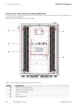
Number of strings
16
24
32
Sealing range cable entry
5 mm to 8 mm
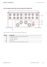
Input cable glands entry (per pole)
4 PG32 with 4 input
each
6 PG32 with 4 input
each
8 PG32 with 4 input
each
Input connection
Directly on Fuse Holder
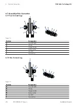
Conductor cross-section
4 mm
2
to 6 mm
2
Fuse holder
DIN Rail Mounting - 1 pole - 1,500 V
DC
Fuse type
10/14x85 - 1,500 V
DC
- gPV
Fuse size
10 A to 30 A
10 A to 30 A
10 A to 30 A
DC OUTPUT DATA
Output cable glands
Nr. 1 M50x1.5 (with
reduction) per pole
Nr. 2 M50x1.5 (with
reduction) per pole
Nr. 2 M50x1.5 (with
reduction) per pole
Clamping Area
17 mm to 38 mm
17 mm to 38 mm
17 mm to 38 mm
Conductor Material
Copper or aluminium
Terminal Type
Copper busbar with M12 screw
Switch Type
Under Load Switch-Disconnector - 3 pole - 1,500 V
DC
SPD Protection
SPD Type II 15 kA/40 kA
SPD Iscpv
6,000 A
(Note 1) Derating of V
N
versus altitude. 1.0 % per 100 m from 2,001 m to 3,000 m.
1.2 % per 100 m from 3,001 m to 4,000 m.
(Note 2) Derating of 1%/K of max. current from 50°C to 60°C.
11 Technical Data


